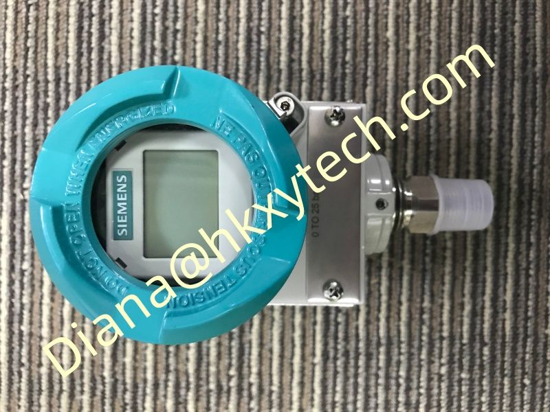
Using SIEMENS 7MF0300-1TD01-5AF2-Z+A00+C11+C12+E01+Y01 for Pump Discharge Pressure Monitoring and Surge-Aware Operation
Pump discharge pressure is often treated as a simple operating value, yet the trend can reveal valve position, blocked lines, pump wear, suction problems and hydraulic transients. The SIEMENS 7MF0300-1TD01-5AF2-Z+A00+C11+C12+E01+Y01 provides a SITRANS P320 gauge-pressure measurement point that can support control and maintenance when its range, mounting and signal treatment reflect the real hydraulic duty.
Read Pressure as Part of a System
A high reading from the SIEMENS 7MF0300-1TD01-5AF2-Z+A00+C11+C12+E01+Y01 may indicate a closed downstream valve, restricted line or high static head. A low reading can result from low speed, worn components, inadequate suction conditions or an open bypass. Pressure alone does not identify the cause, so compare it with flow, pump speed, valve position and suction pressure.
Select a Range That Includes Transients
Normal discharge pressure should occupy a useful part of the SIEMENS 7MF0300-1TD01-5AF2-Z+A00+C11+C12+E01+Y01 calibrated range, while credible startup, shutdown and valve-closure surges remain within allowable limits. Do not use electronic damping as the only protection against pressure spikes. Mechanical design, surge analysis and suitable pressure accessories may be required.
Choose the Tapping Point Carefully
Locate the SIEMENS 7MF0300-1TD01-5AF2-Z+A00+C11+C12+E01+Y01 connection where it represents pump discharge conditions without excessive pulsation or sediment accumulation. Keep the pressure path short, supported and accessible. For liquid service, vent trapped gas; for hot service, protect the transmitter from process temperature according to the approved arrangement.
Turn the Trend into Maintenance Information
Compare SIEMENS 7MF0300-1TD01-5AF2-Z+A00+C11+C12+E01+Y01 pressure at a consistent speed and flow.
Track the pressure difference across filters or restrictions.
Review startup peaks and time to reach steady operation.
Correlate pressure changes with vibration, current and valve travel.
Investigate gradual baseline movement before changing calibration.
Commission the Complete Signal Path
Verify the SIEMENS 7MF0300-1TD01-5AF2-Z+A00+C11+C12+E01+Y01 article number, process connection, range, units, damping and HART tag. Apply traceable pressure points and compare the local display, digital value and control-system indication. Prove alarms and interlocks at their configured thresholds, then save the as-left settings.
Useful pump context
Discharge pressure + suction pressure + flow + speed + valve position provide a stronger diagnosis than any single signal.
Inspect the SIEMENS 7MF0300-1TD01-5AF2-Z+A00+C11+C12+E01+Y01 connection periodically for leakage, blockage and vibration damage. When the instrument is combined with hydraulic context and consistent trending, the SIEMENS 7MF0300-1TD01-5AF2-Z+A00+C11+C12+E01+Y01 becomes more than a pressure display: it supports earlier fault recognition and more confident pump operation.