Replacing SIEMENS 7MF0340-1RM01-5AM2-Z+A00+C11+E01+K84+Y01 During a Plant Turnaround Without Losing the Original Loop Design
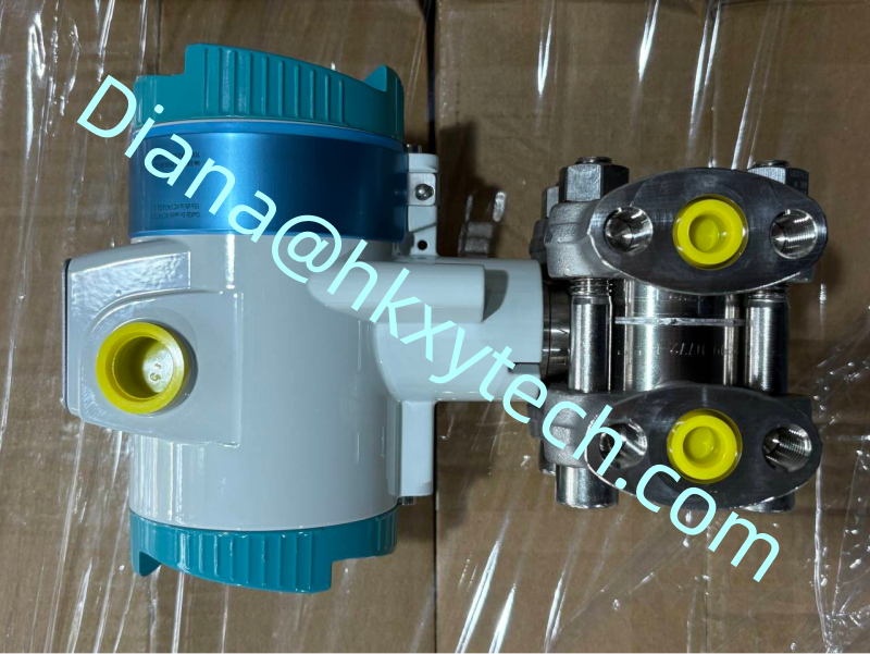
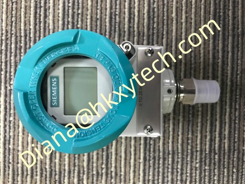
Turnarounds compress months of planning into a short execution window. A pressure transmitter replacement that appears simple can delay startup when the order code, manifold connection, display, approvals or configuration does not match. The SIEMENS 7MF0340-1RM01-5AM2-Z+A00+C11+E01+K84+Y01 should therefore be prepared as a controlled replacement package, not just delivered as a loose instrument.
Before the Shutdown: Build the Replacement Pack
Compare every character of the new SIEMENS 7MF0340-1RM01-5AM2-Z+A00+C11+E01+K84+Y01 with the installed nameplate and approved purchase specification. Confirm the sensor range, process interface, housing, electrical entries, display and option codes. Collect calibration documents and save the current device configuration before the old transmitter becomes unavailable.
Place the SIEMENS 7MF0340-1RM01-5AM2-Z+A00+C11+E01+K84+Y01, required seals, bolts, bracket, glands, identification plate and test adapters in one tagged kit. A missing cable gland or incompatible flange thread can consume more turnaround time than the transmitter replacement itself.
At Removal: Capture Evidence Before Disturbing the Loop
Record the old reading, manifold position and HART configuration. Photograph high- and low-pressure connections, tubing slope and grounding. Inspect for deposits, corrosion, trapped liquid or damaged fittings. These observations help determine whether the old SIEMENS 7MF0340-1RM01-5AM2-Z+A00+C11+E01+K84+Y01 equivalent actually failed or whether the pressure path caused the reported problem.
On the Bench: Configure with Intent
Enter the approved tag, lower and upper range values, units, damping, transfer function and fault response into the SIEMENS 7MF0340-1RM01-5AM2-Z+A00+C11+E01+K84+Y01. Do not copy every parameter blindly from the removed device; compare them with the current loop design. Apply traceable test points and retain the as-left results.
Turnaround release package
Verified order code | Accessories | Saved configuration | Bench test | Installation photos | Leak test | Loop test | Restoration sign-off
At Installation: Protect the New Device
Mount the SIEMENS 7MF0340-1RM01-5AM2-Z+A00+C11+E01+K84+Y01 without forcing the tubing into position. Check valve orientation and keep the equalizer open during the appropriate initial pressure sequence. Leak-test connections under the site procedure, then bring the transmitter into service without uncontrolled one-sided pressure.
Before Startup Release
Prove the SIEMENS 7MF0340-1RM01-5AM2-Z+A00+C11+E01+K84+Y01 signal at the local display, HART interface and control system. Confirm square-root extraction and alarm direction where applicable. Restore all bypasses and manifold valves, then obtain operations sign-off on the final lineup.
Update the asset record with the new SIEMENS 7MF0340-1RM01-5AM2-Z+A00+C11+E01+K84+Y01 serial number, configuration and test evidence. A disciplined replacement preserves the loop design, reduces startup uncertainty and leaves maintenance teams with a clear history instead of an undocumented instrument swap.