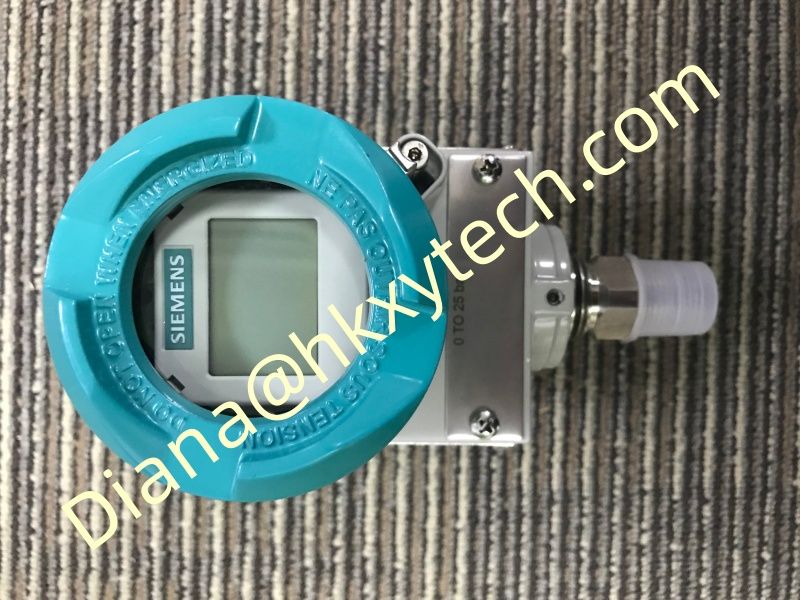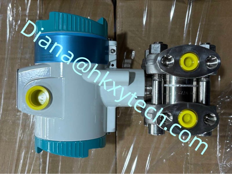
SIEMENS 7MF0340-1RN01-5AF2-Z+A00+C11+C12+E01+K84+Y01 Maintenance FAQ: Practical Answers for Differential Pressure Technicians
The SIEMENS 7MF0340-1RN01-5AF2-Z+A00+C11+C12+E01+K84+Y01 belongs to the SITRANS P320 platform for differential-pressure and flow applications. The questions below focus on decisions that technicians face after installation, when the instrument must be checked without losing configuration history or mistaking process-side faults for transmitter faults.
Why does the SIEMENS 7MF0340-1RN01-5AF2-Z+A00+C11+C12+E01+K84+Y01 show a non-zero value when the process is stopped?
Stopped flow does not always create zero differential pressure. Check whether both sides can be safely equalized, whether liquid levels differ in the impulse lines and whether valves are leaking through. Establish a valid reference condition before applying zero trim to the SIEMENS 7MF0340-1RN01-5AF2-Z+A00+C11+C12+E01+K84+Y01.
Should damping be increased when the reading fluctuates?
Only after the source is understood. Pulsating pumps, flashing liquid, vibration, poor impulse routing or electrical interference can all create fluctuation. Increasing damping in the SIEMENS 7MF0340-1RN01-5AF2-Z+A00+C11+C12+E01+K84+Y01 may make the trend look smoother while delaying detection of a real process change.
How can the transmitter be checked without removing it?
Use approved isolation, equalizing and test connections. Record the as-found SIEMENS 7MF0340-1RN01-5AF2-Z+A00+C11+C12+E01+K84+Y01 output, then apply traceable pressure points within the configured range. Compare local display, HART and control-system values. Never improvise a pressure connection on a live process.
What must be saved before replacing the device?
Save the complete SIEMENS 7MF0340-1RN01-5AF2-Z+A00+C11+C12+E01+K84+Y01 order code, serial number, device revision, range, units, damping, transfer function, fault-current behavior, tag and any application-specific parameters. Photograph the manifold and tubing before removal so the replacement is not blamed for an existing installation error.
Can another 7MF0340 transmitter be used as a direct substitute?
Not without a full comparison. Sensor span, flange thread, wetted materials, housing, display, approvals and option certificates can differ. The replacement should match the complete SIEMENS 7MF0340-1RN01-5AF2-Z+A00+C11+C12+E01+K84+Y01 configuration or pass an approved engineering equivalence review.
What should the maintenance report contain?
Original symptom and operating condition
Valve positions and pressure-path findings
As-found and as-left SIEMENS 7MF0340-1RN01-5AF2-Z+A00+C11+C12+E01+K84+Y01 readings
Configuration changes with authorization
Leak test, loop test and restoration confirmation
When should engineering become involved?
Escalate repeated drift, unexplained overrange events, process-material concerns, approval changes or any proposed range and safety-function modification. The SIEMENS 7MF0340-1RN01-5AF2-Z+A00+C11+C12+E01+K84+Y01 should remain tied to its original design basis unless formal change control authorizes a new one.
Consistent answers and good records make the SIEMENS 7MF0340-1RN01-5AF2-Z+A00+C11+C12+E01+K84+Y01 easier to maintain. The goal is not merely to restore a number on the display, but to prove that the pressure path, configuration and complete control loop are trustworthy.