Verifying SIEMENS 7MF0300-1QD01-5AF2-Z+A00+C11+C12+C20+E01+Y01 in a Protective Gauge-Pressure Loop: From Process Connection to Trip Evidence
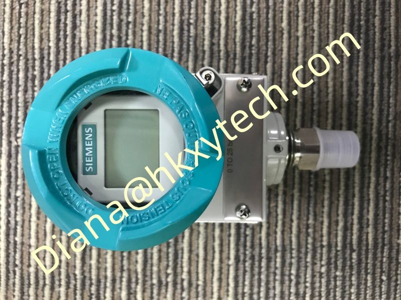
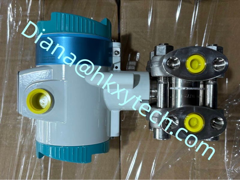
The SIEMENS 7MF0300-1QD01-5AF2-Z+A00+C11+C12+C20+E01+Y01 is a SITRANS P320 gauge-pressure transmitter configuration. In a protective loop, measurement accuracy matters, but dependable trip performance requires more: the pressure must reach the sensor, the configured range must match the safety basis, the logic solver must interpret the signal correctly and testing must reveal hidden failures.
Define the Pressure Event
State whether the SIEMENS 7MF0300-1QD01-5AF2-Z+A00+C11+C12+C20+E01+Y01 protects against high pressure, low pressure or loss of pressure. Identify the normal range, alarm point, trip point, maximum credible pressure and required response time. Confirm that pulsation dampers, root valves or small-bore connections do not delay the event beyond the process-safety requirement.
Check the Physical Measurement Path
Inspect the process thread, root valve, tubing and any seal arrangement connected to the SIEMENS 7MF0300-1QD01-5AF2-Z+A00+C11+C12+C20+E01+Y01. Look for blockage, trapped gas in liquid service, trapped liquid in gas service and temperature conditions that could affect the measurement. A perfect electrical simulation cannot prove a blocked pressure connection.
Verify the Configured Behavior
Read the SIEMENS 7MF0300-1QD01-5AF2-Z+A00+C11+C12+C20+E01+Y01 range, units, damping, tag and fault-current setting through HART. Compare each safety-relevant parameter with the approved requirement. Lock or control configuration access according to site practice, and record the delivered hardware and firmware revision.
Run a Layered Functional Test
Apply known pressure to the SIEMENS 7MF0300-1QD01-5AF2-Z+A00+C11+C12+C20+E01+Y01 and record as-found values.
Approach the alarm and trip points from the normal operating direction.
Confirm analogue input, diagnostic status and logic-solver action.
Prove the final protective action under the authorized test arrangement.
Restore the process connection, bypasses and configuration.
Where option C20 is used for a safety-related application, consult the current Siemens safety documentation for the exact SIEMENS 7MF0300-1QD01-5AF2-Z+A00+C11+C12+C20+E01+Y01 configuration. The proof-test method and interval should follow the project safety-requirement specification and failure assumptions, not a generic maintenance interval.
Keep Evidence That Can Be Audited
The final record should include applied pressures, reference-equipment identification, as-found and as-left SIEMENS 7MF0300-1QD01-5AF2-Z+A00+C11+C12+C20+E01+Y01 results, observed trip value, final-element response, bypass restoration and authorization. Record any adjustment separately from the proof-test result.
The SIEMENS 7MF0300-1QD01-5AF2-Z+A00+C11+C12+C20+E01+Y01 contributes dependable gauge-pressure information when the complete path from process connection to protective action is engineered and tested. A valid proof test demonstrates the loop's behavior; it does not merely show that the transmitter display changes.