Coordinating the Sensor Input, Analog Indication and Two Alarm Contacts of Yokogawa VJU7-026-UAT0 in a Temperature Monitoring Circuit
Temperature conversion is useful when the sensor signal and receiving equipment need a defined interface. Yokogawa VJU7-026-UAT0 is a JUXTA universal temperature converter reference. Its documented code structure distinguishes the input family, first analog output and second alarm-output function; the configured sensor type and range still need to be specified.
Start with the sensing element
For Yokogawa VJU7-026-UAT0, specify the exact sensor type and how its conductors reach the converter. An RTD request should identify the element standard and wiring arrangement; a thermocouple request should identify its type and connection materials.
Record the required engineering range alongside Yokogawa VJU7-026-UAT0. A universal input capability does not mean a newly supplied unit will already carry the configuration used by the existing process.
A converter change can alter displayed temperature
The receiving system scaling must agree with the configuration of Yokogawa VJU7-026-UAT0. Save both ends of that relationship before replacing the module. If the range changes intentionally, ensure the displayed units and alarm thresholds are reviewed together. A correct current output from Yokogawa VJU7-026-UAT0 can still produce an incorrect operator value when the receiver retains a different span.
| Ordering reference | Yokogawa VJU7-026-UAT0 |
|---|---|
| Input family | Thermocouple, RTD or mV input |
| Code 6 supply | 100 to 240 V AC/DC, subject to published tolerance |
| Output A | 4 to 20 mA DC |
| Second output T | Alarm output with two relay contacts |
| Required configuration | Input type, measuring range and burnout behavior |
| Series | Yokogawa JUXTA VJU7 |
Analog value and alarm event
Treat the analog signal from Yokogawa VJU7-026-UAT0 separately from the alarm contacts. One represents a continuous measurement, while the others communicate defined events to their receiving circuits. Record how each destination uses its signal.
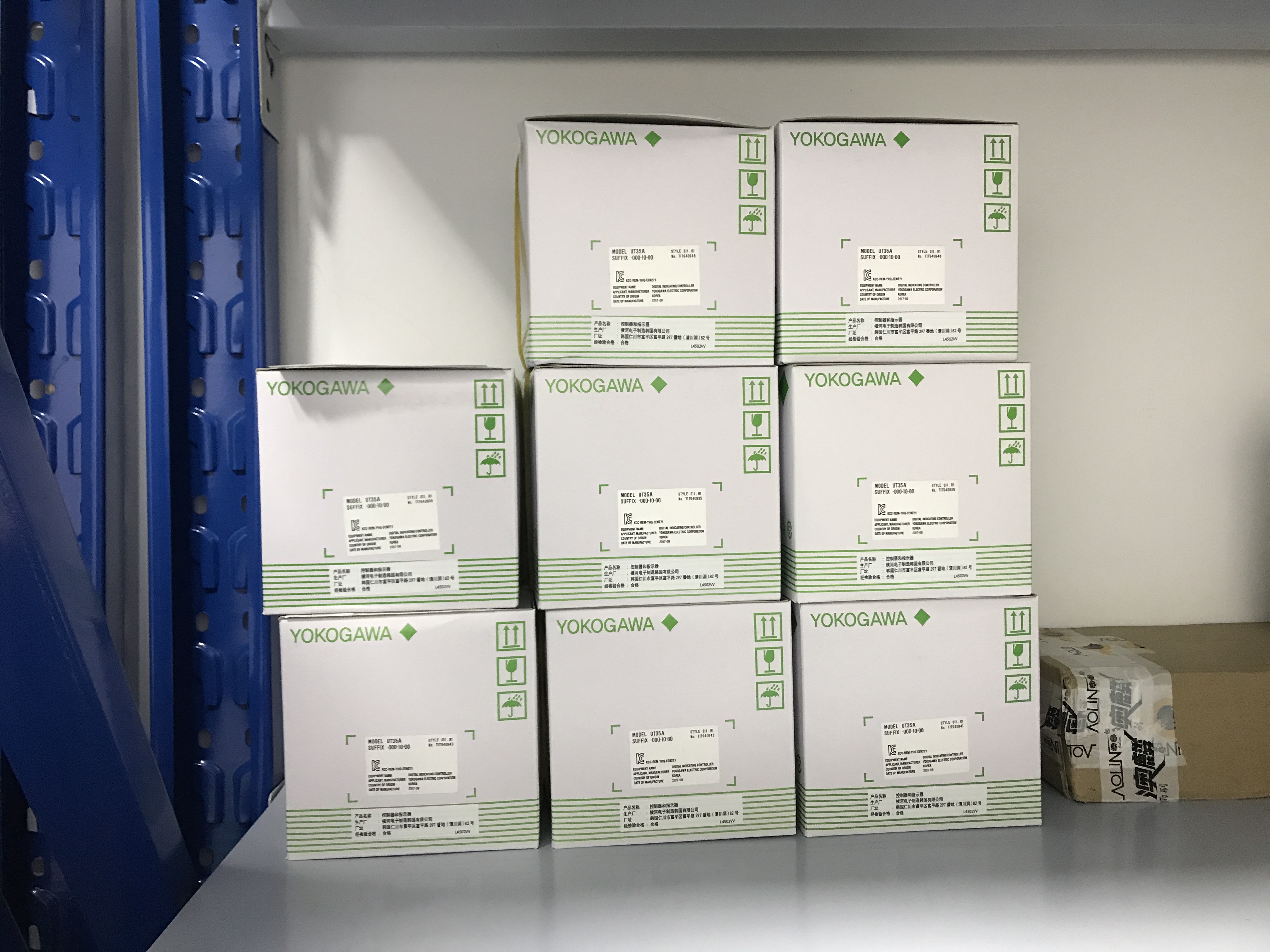
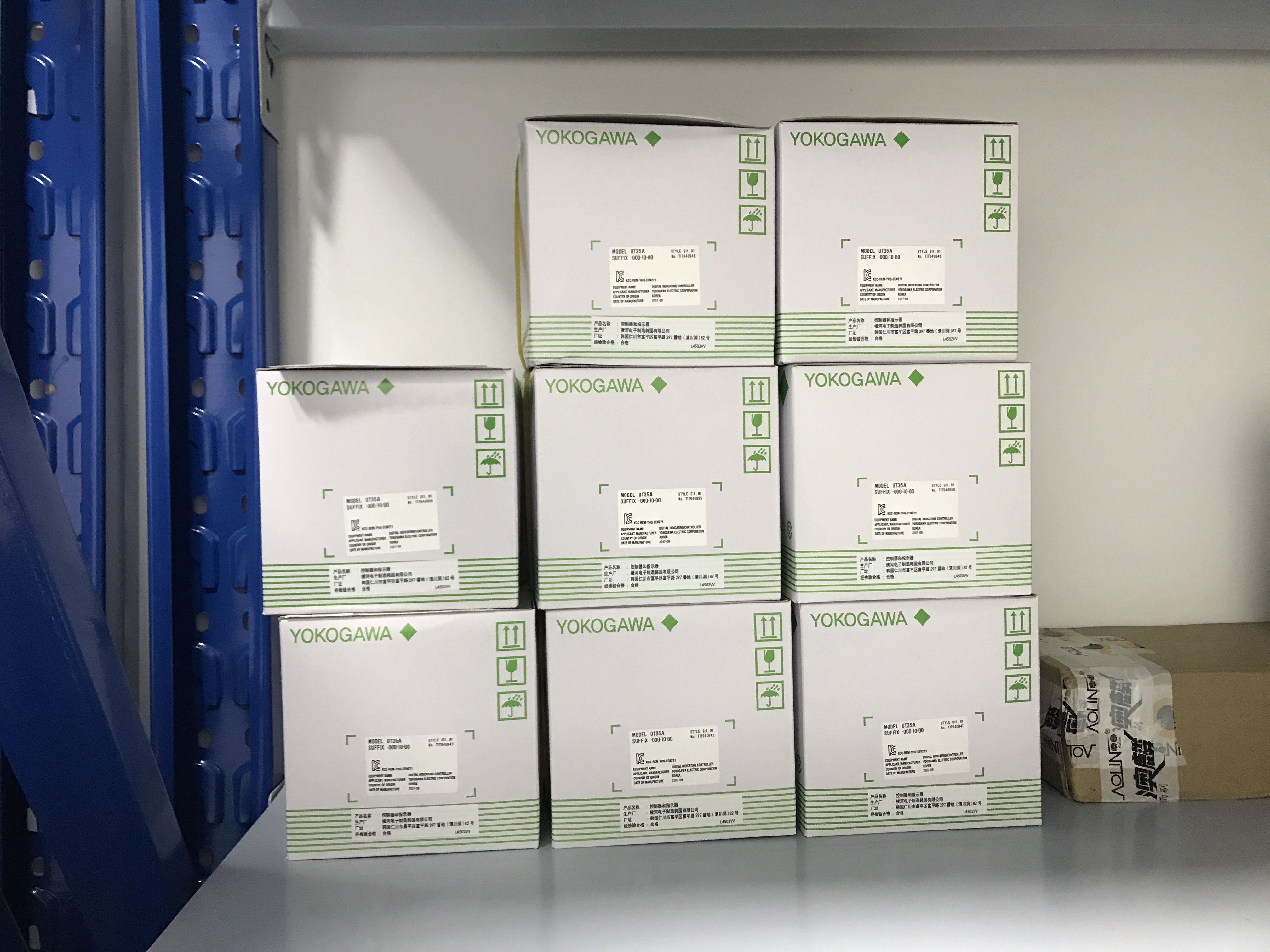
Shared reference image for Yokogawa VJU7-026-UAT0. The supplied list associates this brand stock image with the request; it is not a photograph confirming the exact model, configuration or accessories offered.
Follow each contact to its load
Identify the circuits switched by the alarm contacts of Yokogawa VJU7-026-UAT0 and compare them with the applicable contact ratings. Keep the normal and alarm states documented at the receiving equipment. Do not assume that an alarm contact supplies its own load power. The drawing for Yokogawa VJU7-026-UAT0 should make those power and signal paths readable to the technician checking the installation.
Set the alarm behavior deliberately
When ordering Yokogawa VJU7-026-UAT0, state the intended alarm behavior and settings rather than relying on the output letter alone. Include the required response to sensor failure in the configuration review.
Supply a configuration with the order
A purchase request for Yokogawa VJU7-026-UAT0 should include the full code, sensor specification, range, alarm requirements and quantity. State whether configuration service and any separately supplied setting tools are needed. On receipt, compare the delivered label and configuration record with the request. The shared image for Yokogawa VJU7-026-UAT0 is a brand reference; it does not establish the exact terminals, settings or supplied accessories.