ABB PDS300.M.S9.A.1.A.A.2.A.H-.D1.HAA.BC.CF Configured Differential Pressure Transmitter for Liquid, Gas and Steam Service Accurate Flow, Tank Level and Industrial Process Pressure Measurement in Demanding Applications
ABB PDS300.M.S9.A.1.A.A.2.A.H-.D1.HAA.BC.CF is a configured PDS300 differential pressure transmitter for continuous process measurement. The PDS300 is ABB’s all-rounder DP-style transmitter and can be applied to liquid, gas or steam services. Depending on the primary element and installation, the measured differential pressure can be used for direct pressure monitoring, flow calculation or liquid-level measurement in open and closed vessels.

One transmitter platform for several measurement duties
- Flow: measure differential pressure across an orifice plate, venturi, nozzle or other compatible primary element.
- Level: calculate hydrostatic level in open or pressurized tanks using the correct high- and low-pressure connections.
- Filter monitoring: identify increasing pressure drop across filters, strainers or process equipment.
- Process pressure: monitor differential or related pressure conditions in liquid, gas and steam systems.
PDS300 family performance and usability
ABB specifies a base accuracy of 0.055% of calibrated span for the PDS300 family. The platform supports 4–20 mA with HART and local configuration through keys on the LCD indicator. Available family options cover a wide range of sensor spans, process materials, manifolds and certifications. The exact performance, working-pressure limit and environmental rating of this unit must be determined from the complete order code and the final calibrated data rather than from the PDS300 family name alone.
Define the real operating envelope first
A reliable selection starts with normal, minimum and maximum differential pressure, static line pressure, process temperature and ambient temperature. Also record the medium, density where relevant, expected overpressure, required turndown and response time. For flow service, include the primary-element calculation and square-root extraction responsibility. For level service, document vessel pressure, tapping elevations, wet or dry leg arrangement and any density variation that affects calibration.
Mechanical and materials checks for replacement work
- Confirm process flange type, pressure class, bolt pattern and vent or drain orientation.
- Verify diaphragm, flange, gasket and other wetted materials against the process fluid.
- Match manifold style, mounting bracket, impulse-line routing and transmitter orientation.
- Check housing material, electrical entries, blanking plugs and environmental sealing.
- Confirm the required hazardous-area certification and the approved wiring method.
Keep the complete configuration identity on the RFQ
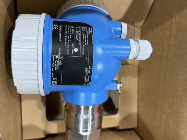
Request ABB PDS300.M.S9.A.1.A.A.2.A.H-.D1.HAA.BC.CF exactly as written. Include the existing nameplate photograph, lower and upper range values, engineering units, required output, display arrangement and approval documents. Ask the supplier to identify any proposed deviation from the full code. This is especially important when a transmitter is replacing an installed unit connected to an existing manifold or impulse-line arrangement.
Commissioning checks before returning the loop to service
After mounting, confirm that the high- and low-pressure sides are connected correctly and that the impulse lines are filled, vented or drained for the application. Verify the calibrated range, zero point, damping, transfer function, alarm direction and tag information. Perform a loop test from the transmitter to the control system, inspect for leaks and document the final configuration. A stable zero should only be established under a verified equal-pressure condition.