Tracing the master backplane, output modules and host cable associated with MTL CPY-C3-ADV551-M before replacing a cabinet interface
Published MTL interface combination
| Item | Identification or selection information |
|---|---|
| Host reference | Yokogawa ADV551 |
| Backplane role | CPY-C3-ADV551-M master arrangement |
| Published function | 16-channel digital output with line fault detection |
| Cable reference in MTL selection guide | AKB331 |
| Associated MTL modules | MTL4524 / MTL4525 / MTL4523R; review documented qualifications and actual assembly |
Trace the signal path from the host
- The MTL selection guide identifies MTL CPY-C3-ADV551-M in a Yokogawa ADV551 interface arrangement.
- Begin with the host I/O reference, then trace the cable and mounted interface modules.
- This approach identifies what the backplane actually connects in the cabinet.
- For MTL CPY-C3-ADV551-M, the host record is a better starting point than a close-up image of one connector because it captures the intended signal path.
Master and companion arrangements
The -M designation should remain visible throughout procurement. MTL documentation also lists an -S arrangement, and the relationship between the two must be checked against the installed design. Do not substitute an -S board for MTL CPY-C3-ADV551-M merely because both names contain ADV551. Document the complete cabinet assembly, including any companion board, so the supplier can review MTL CPY-C3-ADV551-M in the correct context.
What the selection table establishes
The table records the published host, function and cable references without treating every possible module combination as identical. The MTL guide includes qualifications for the associated output modules. For MTL CPY-C3-ADV551-M, obtain the applicable connection documentation and check it against the modules actually installed. A selection-guide entry is useful evidence, but it is not a substitute for the project wiring diagram or the complete manufacturer instructions.
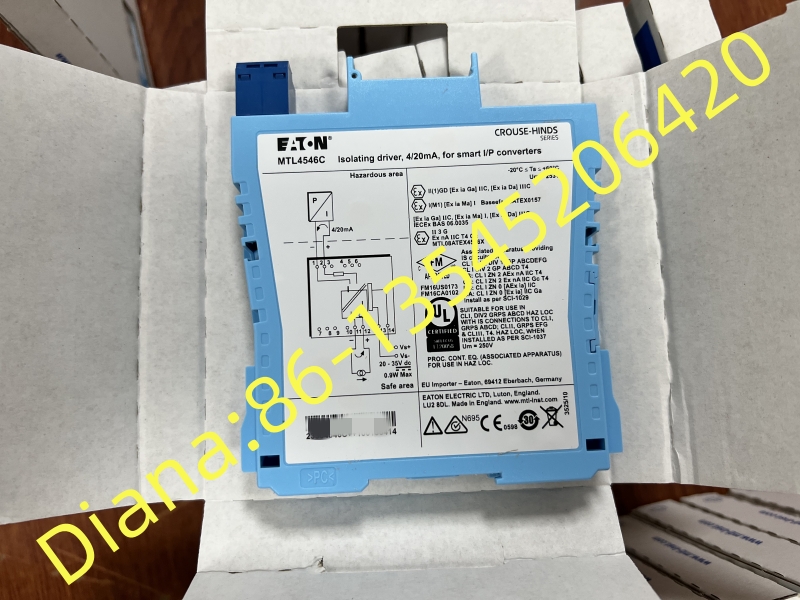
Shared reference image for MTL CPY-C3-ADV551-M. The pictured equipment may differ from the exact ordered assembly; use the full part number and configuration record for identification.
Keep modules separate in the bill of materials
A backplane quotation should explain whether interface modules are included. List their full references individually if a populated arrangement is required. The same applies to the host cable and mounting components. For MTL CPY-C3-ADV551-M, a clear bill of materials prevents a bare board from being confused with the complete cabinet assembly. It also allows the buyer to retain serviceable components where the approved maintenance plan permits.
Line fault detection belongs to the complete loop
The published interface function includes line fault detection, but the behavior seen by the control system depends on the complete arrangement and its configuration. Record the existing field circuit and diagnostic expectations when reviewing MTL CPY-C3-ADV551-M. The responsible system personnel should establish how the replacement will be checked. Do not assume that fitting MTL CPY-C3-ADV551-M alone confirms the diagnostic performance of every connected output.
A useful shutdown package
Prepare the cabinet location, host channel references, cable identification and current assembly photographs before the scheduled work. Include the approved replacement scope and the relevant MTL documentation for MTL CPY-C3-ADV551-M. This gives maintenance personnel a concrete comparison at the work point. It also helps distinguish a planned like-for-like replacement from a change involving another output module or host interface.
Related codes are not interchangeable shorthand
CPY-C3-ADV551L-M and other nearby codes appear in MTL literature, but their published combinations differ. Preserve the exact MTL CPY-C3-ADV551-M reference in the order and require any alternative to be explained. A supplier comparison should identify the host cable, associated modules and intended function. For MTL CPY-C3-ADV551-M, the final acceptance record should link the supplied label to the cabinet drawing and the approved component list.
Documentation basis: manufacturer reference for the product or family. Configuration-dependent details must be reconciled with the complete order code and supplied unit.