Aligning the magnetic float travel and transmitter span of ABB AT200/TW/L/A/R1/M4A/X/CEX/762 MM with an existing level gauge chamber

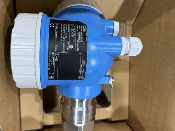
Reference image supplied for ABB AT200/TW/L/A/R1/M4A/X/CEX/762 MM. This shared image may show other equipment; it does not identify the exact ordered configuration.
Coordinate mounting, configuration and the final indication
External mounting still requires the correct relationship between the transmitter sensor and the magnetic float. Confirm the required mounting hardware and compatibility with the gauge rather than inferring these from the transmitter enclosure. The site should use the applicable manufacturer procedures when installing and checking the assembly.
For ABB AT200/TW/L/A/R1/M4A/X/CEX/762 MM, retain the selected process variable, output configuration and scaling used by the receiving system. After the approved work, compare the indicated level with the required commissioning reference and document the final settings. Keep the complete transmitter code alongside the gauge identification and installation drawing. If an AT100, AT600 or another family is proposed as an alternative, request a specific assessment of the mounting and functional differences instead of treating related model names as evidence of interchangeability.
The gauge and transmitter work together
ABB AT200/TW/L/A/R1/M4A/X/CEX/762 MM is an AT200 magnetostrictive transmitter configuration for use with a compatible magnetic level gauge. Selection of ABB AT200/TW/L/A/R1/M4A/X/CEX/762 MM should therefore include the chamber and float arrangement, rather than evaluating the transmitter as an isolated vessel probe.
AT200 configuration and mounting data
| Characteristic | Details and selection notes |
|---|---|
| Measurement principle | Magnetostrictive float-position measurement |
| Mounting arrangement | External mounting on a compatible magnetic level gauge |
| Specified length | 762 mm in the supplied order; confirm the measurement references on the drawing |
| Electronics and approvals | Check /M4A, /CEX and the complete suffix against the supplied configuration |
Relate the transmitter to the gauge and its float
An external magnetostrictive transmitter reads the position associated with the magnetic float arrangement of a compatible level gauge. The gauge chamber, float and transmitter therefore need to be considered together. Identify the gauge model and the intended measurement duty before evaluating the transmitter as a replacement.
For ABB AT200/TW/L/A/R1/M4A/X/CEX/762 MM, provide the relevant gauge drawing and describe the installed sensor position. If the application involves more than one possible level or an interface arrangement, confirm which variable the system is intended to report. The external mounting concept should not be confused with a directly inserted vessel probe. A clear description of the actual gauge assembly is more useful than a broad request for a level transmitter with an approximately similar length.
Locate the active travel
The supplied ABB AT200/TW/L/A/R1/M4A/X/CEX/762 MM string includes 762 MM, but the drawing must establish whether that dimension refers to the required active span or another assembly length. Compare the mounting reference and float travel before approving ABB AT200/TW/L/A/R1/M4A/X/CEX/762 MM for the installed gauge.
External mounting requirements
For ABB AT200/TW/L/A/R1/M4A/X/CEX/762 MM, inspect the available mounting location and the relationship between the sensor and the magnetic float. Confirm the required brackets and gauge compatibility with the supplier; the body appearance of ABB AT200/TW/L/A/R1/M4A/X/CEX/762 MM does not establish those installation details.
Define what the 762 mm dimension represents
The supplied order string includes a length, but the correct comparison requires its meaning on the assembly drawing. Establish the reference points used for the dimension and compare them with the available float travel and installed mounting position. Do not assume that the stated length is automatically the full active measurement span or the total physical length of every component.
When ordering ABB AT200/TW/L/A/R1/M4A/X/CEX/762 MM, ask for a dimensioned drawing that shows the relevant sensor arrangement and mounting references. Compare it with the existing installation before the maintenance work begins. If a different length is proposed, have the change reviewed against the gauge and the intended output span. This prevents a seemingly small dimensional difference from being accepted without understanding its effect on the level measurement.
Preserve the process variable
Before replacing ABB AT200/TW/L/A/R1/M4A/X/CEX/762 MM, record the configured variable and the output scaling used by the control system. Other AT-series transmitters may use a different installation arrangement, so any alternative to ABB AT200/TW/L/A/R1/M4A/X/CEX/762 MM needs a gauge-specific comparison and configuration review.
Technical reference: Manufacturer product information. Configuration-dependent ratings must be checked against the complete order and supplied nameplate.