Tracing the controller-to-field output path through Pepperl Fuchs MB-C3-DO32-AKB-131972 before replacing a termination board in a marshalling cabinet
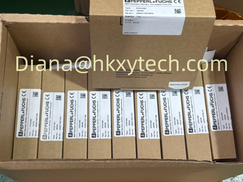
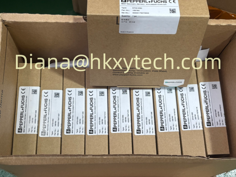
Reference image supplied for Pepperl Fuchs MB-C3-DO32-AKB-131972. This shared image may show other equipment; it does not identify the exact ordered configuration.
Trace the output path from controller to field wiring
A termination board sits within a larger signal path. The controller I/O card, system cable, interface modules and field terminals each contribute to the final arrangement. Begin the review with a drawing that shows those connections together. This is particularly helpful when the cabinet contains several similar boards serving different signal directions.
For Pepperl Fuchs MB-C3-DO32-AKB-131972, identify the exact output arrangement and the installed connector assignments. A board-level replacement should preserve the approved mapping between controller channels and field circuits. The model name provides a useful starting point, but the cabinet drawing and installed module population establish how the particular assembly is actually used.
Organize the exchange by channel and assembly position
Before an approved replacement, capture the installed identification and label the relevant connections according to the site's procedures. Keep a record of the board position and connected circuits so that the verification work can follow the actual channel mapping. Work on a marshalling assembly should be planned around the process and control-system requirements of the site.
After replacing Pepperl Fuchs MB-C3-DO32-AKB-131972, the responsible team should verify the intended output path and associated indications under the approved test plan. Preserve the final component list and drawing revision with the cabinet records. These details make future spare selection and troubleshooting more precise than a generic description of an interface board.
Output interface board reference
| Characteristic | Details and selection notes |
|---|---|
| Component family | MB-C3 termination / interface board |
| Signal direction | Digital output, per manufacturer selection catalog |
| Catalog association | KFD2-SL2-Ex2 shown with this board |
| Connection details | Confirm system cable, channel mapping and board revision from the assembly drawing |
Start at the cabinet drawing
Pepperl Fuchs MB-C3-DO32-AKB-131972 is identified in the manufacturer selection material as a digital output interface board. For a replacement involving Pepperl Fuchs MB-C3-DO32-AKB-131972, trace the controller connection, installed interface modules and field terminals as a complete assembly rather than selecting the board from a generic module picture.
Separate the board specification from the module specification
The termination board and its associated interface modules perform different roles. Electrical characteristics attributed to an individual module should not automatically be described as characteristics of the bare board. Likewise, an application approval depends on the selected arrangement and relevant documentation, not on the board name alone.
A request for Pepperl Fuchs MB-C3-DO32-AKB-131972 should list the interface modules separately when they are needed. State whether existing modules will be transferred or whether a populated assembly is required. If the supplier offers an assembled board, request a component list so that the technical comparison covers the actual delivered scope rather than an unspecified combination.
Output direction is essential
A similar MB-C3 input board is not equivalent to Pepperl Fuchs MB-C3-DO32-AKB-131972. Check the signal direction and the actual channel wiring before specifying Pepperl Fuchs MB-C3-DO32-AKB-131972, including the relationship between the system cable connectors and the field-side output circuits.
Board and modules are separate scope
The catalog links Pepperl Fuchs MB-C3-DO32-AKB-131972 with a KFD2-SL2-Ex2 arrangement. Confirm whether a quotation for Pepperl Fuchs MB-C3-DO32-AKB-131972 covers the bare termination board or includes mounted modules, cables and accessories; the photographed reference equipment should not be used to infer the package contents.
Connector layout and revision deserve a close comparison
A change in board revision can affect a replacement review even when the overall family designation remains familiar. Compare labels, connector positions, mounting points and any documented revision differences before accepting the incoming part. The goal is to establish that the supplied board is appropriate for the installed assembly without making assumptions from the photograph.
For Pepperl Fuchs MB-C3-DO32-AKB-131972, include the system cable identification and any relevant cabinet wiring references in the technical file. If a different suffix or board revision is offered, ask the supplier to explain the change and provide the applicable compatibility information. That explanation should precede installation, not be discovered during a shutdown.
Revision and connector comparison
Before accepting Pepperl Fuchs MB-C3-DO32-AKB-131972, compare connector keying, mounting points and the installed board revision. Related MB-C3 products may serve different I/O arrangements, so preserve the 131972 suffix of Pepperl Fuchs MB-C3-DO32-AKB-131972 and resolve any proposed revision change against the original cabinet documentation.
Technical reference: Manufacturer product information. Configuration-dependent ratings must be checked against the complete order and supplied nameplate.