Non-contact surface tracking with ABB LLT100.AI.B.H.10.L5-E03 when vessel access and beam alignment shape the installation
From vessel roof to product surface
ABB LLT100.AI.B.H.10.L5-E03 belongs to the LLT100 non-contact laser measurement family. A project evaluating ABB LLT100.AI.B.H.10.L5-E03 should begin with the distance to the lowest operating surface, the nozzle position and the intended target area; these determine whether a clear measurement path is available throughout filling and emptying.
Design the measuring path around the filling cycle
Consider a storage silo in which material enters from one side and forms a changing surface profile. The best measuring point is not necessarily the center of the roof: the nozzle position, filling stream and internal supports all influence what the transmitter sees. For ABB LLT100.AI.B.H.10.L5-E03, the application drawing should show the intended target area at both the high and low operating levels. This gives the instrument supplier a practical basis for reviewing the proposed mounting arrangement.
A useful site survey includes the nozzle length and opening, nearby obstructions, access for alignment and the position of any cleaning equipment. Describe temporary conditions during filling as well as normal steady operation. An installation that appears unobstructed when the vessel is empty may present a different measurement path during production.
Commissioning observations worth keeping
During an engineering-approved commissioning check, compare the displayed value with an independent reference at known operating conditions. Retain the configured span, mounting reference and relevant diagnostic observations with the instrument record. If the reading changes unexpectedly, that record helps distinguish a process change from an alignment, scaling or optical-window issue.
The replacement file for ABB LLT100.AI.B.H.10.L5-E03 is most useful when it contains photographs of the installed orientation as well as the nameplate. Record any application-specific accessories separately from the transmitter code. These details make a later spare purchase more accurate without turning a reference photograph into a claim about the exact supplied configuration.
Laser transmitter configuration
| Characteristic | Details and selection notes |
|---|---|
| Technology | LLT100 laser distance and level measurement |
| Series communication | Two-wire powered with HART; confirm ordered electronics |
| Body code AI | Aluminum housing, 1/2 in NPT electrical entry |
| Flange and accessories | Confirm B, H, 10, L5 and E03 against the complete factory code |
Aiming matters more than a photograph
For ABB LLT100.AI.B.H.10.L5-E03, identify ladders, internal bracing and incoming material streams that could intercept the beam. Review the mounting angle before specifying ABB LLT100.AI.B.H.10.L5-E03; an accessible aiming arrangement can make inspection easier without assuming that a swivel flange, dust tube or heating accessory is included in this exact order.
Turn a distance reading into a useful level indication
The transmitter measures along its line of sight, while operators usually want a level relative to a vessel datum. Before commissioning, establish the reference plane and the intended empty and full points. Check that the engineering units in the control system agree with the local setup, and distinguish the physical vessel height from the operating span used for the signal.
When ABB LLT100.AI.B.H.10.L5-E03 is used for inventory monitoring, a level value is not automatically a mass or volume value. Vessel geometry and the material profile may require a separate conversion in the control or inventory system. State which quantity the project needs so that instrument configuration and downstream calculations are reviewed together.

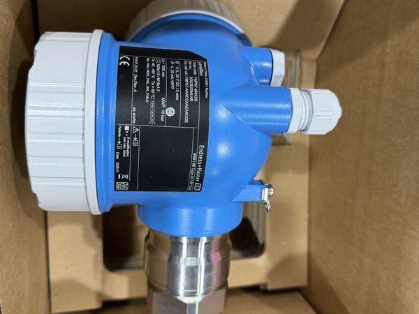
Reference image supplied for ABB LLT100.AI.B.H.10.L5-E03. This shared image may show other equipment; it does not identify the exact ordered configuration.
Dust, splash and the optical window
Use the actual process conditions to assess window protection for ABB LLT100.AI.B.H.10.L5-E03. Intermittent dust clouds, deposits and condensation are different problems, so a proposed ABB LLT100.AI.B.H.10.L5-E03 installation needs an application review rather than a blanket claim that every accessory or environmental rating applies to this code.
Separate the transmitter from its mounting accessories
A complete installation may require a mounting arrangement that supports aiming, inspection or protection of the optical window. Those requirements should be described explicitly in the quotation request. A transmitter-only line item does not establish the presence of a bracket, flange adapter, dust protection accessory or other installation hardware.
For ABB LLT100.AI.B.H.10.L5-E03, compare the proposed supply scope with what is already available at the site. If existing accessories will be retained, provide their dimensions and identification. If a new assembly is required, request a drawing showing the complete mechanical interface. This prevents a technically correct transmitter from arriving without the parts needed to mount it in the planned position.
Matching a replacement
Compare ABB LLT100.AI.B.H.10.L5-E03 with the installed LLT100 nameplate, flange drawing and configured measuring span. Another LLT100 may share the measurement principle while using different connections; retain the full ABB LLT100.AI.B.H.10.L5-E03 designation when requesting the flange dimensions and final configuration sheet.
Technical reference: Manufacturer product information. Configuration-dependent ratings must be checked against the complete order and supplied nameplate.