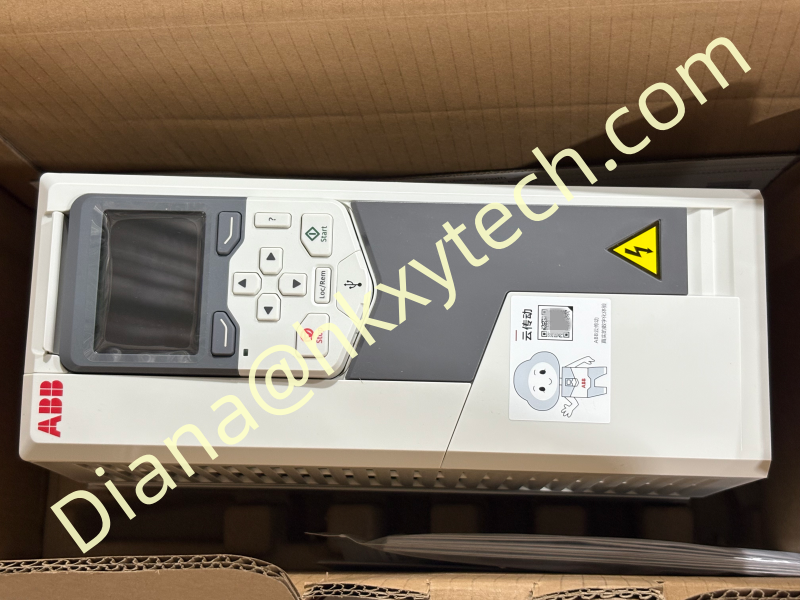
Following the Signal Through ABB ACQ580-01-07A3-4+B056
A water-control drive can be understood as a chain of information. ABB ACQ580-01-07A3-4+B056 receives a process measurement, compares it with an operating target, changes motor speed and then watches the result. This ACQ580 configuration is for a 380 to 480 V three-phase supply and includes +B056 IP55 / UL Type 12 protection. Its nominal 400 V reference is 7.2 A, 3.0 kW, frame R1.
The process begins in the pipe or tank
Pressure, level or flow must first be measured at a location that represents the real process. A badly located transmitter can make ABB ACQ580-01-07A3-4+B056 appear unstable even when the drive is responding correctly. Avoid trapped air, pulsation, blocked impulse paths and wiring routes exposed to motor-cable noise. Record the transmitter range and engineering units before scaling the input.
The signal arrives at the control terminals
Confirm whether the signal is current, voltage or a digital status.
Check polarity, shield termination and the common reference.
Verify the live value with an independent measurement where practical.
Name the signal clearly in drawings and the ABB ACQ580-01-07A3-4+B056 parameter record.
Define a safe response for a value below or above the valid range.
ABB ACQ580-01-07A3-4+B056 interprets demand
The controller compares actual pressure or level with the setpoint. Minimum speed prevents operation in an unsuitable pump region; maximum speed limits mechanical and hydraulic stress. Ramps control how quickly ABB ACQ580-01-07A3-4+B056 changes energy delivered to the water. PID settings then determine how firmly and how quickly the system corrects an error.
Good tuning is quiet: the process reaches its target without repeated overshoot, rapid speed changes or unnecessary valve movement.
The motor converts the command into pump work
| Observation | Possible meaning | First check |
|---|---|---|
| Speed rises, pressure does not | Pump not primed, valve issue, leak or wrong rotation | Confirm water path and rotation |
| Current rises sharply | Mechanical restriction or demanding hydraulic point | Compare current with motor and pump data |
| Pressure oscillates | Aggressive tuning, poor sensor location or interacting controls | Trend feedback and ABB $m output |
| Stable speed, noisy signal | Electrical interference or transmitter issue | Inspect shielding and signal wiring |
| Low current and low flow | Dry running, air ingress or lost prime | Stop and protect the pump |
Feedback closes the loop
After every speed change, the water system needs time to react. ABB ACQ580-01-07A3-4+B056 should be tuned with that delay in mind. During commissioning, make controlled demand changes and trend setpoint, actual value, frequency and current. A single snapshot can miss hunting; a short trend shows whether the loop settles or continues to cycle.
Protection interrupts the chain when necessary
Prove the remote stop and local isolation philosophy.
Simulate loss of the process transmitter and witness the configured ABB ACQ580-01-07A3-4+B056 response.
Test dry-run or low-suction protection without exposing the pump to damage.
Verify high-level, low-level or pressure-limit contacts as applicable.
Review the restart policy after power loss and after a trip.
Record each result with date, witness and corrective action.
Electrical and enclosure reference
Before the signal chain is commissioned, verify that ABB ACQ580-01-07A3-4+B056 matches the motor and supply. The -4 code covers 380 to 480 V three-phase service, while +B056 defines the IP55 / UL Type 12 enclosure. Preserve that protection with suitable glands, sealed entries and clean cooling paths. The published nominal 400 V data of 7.2 A and 3.0 kW must still be checked against the exact motor current and site conditions.
A useful commissioning trace
Full model: ABB ACQ580-01-07A3-4+B056
Transmitter range and normal value
Setpoint and minimum/maximum speeds
Motor current at low, normal and high flow
Alarm and interlock results
Final ABB ACQ580-01-07A3-4+B056 parameter backup
When every step of the chain is documented, ABB ACQ580-01-07A3-4+B056 becomes easier to operate and diagnose. The technician can decide whether a problem begins with sensing, control logic, motor loading or the hydraulic process instead of changing parameters at random.