Managing the SIEMENS 7MF0340-1GN01-5AF2-Z+A00+C11+C12+C20+E01+K84+Y01 Across a Safety Instrumented Function Lifecycle
The SIEMENS 7MF0340-1GN01-5AF2-Z+A00+C11+C12+C20+E01+K84+Y01 includes option selections that require careful project review, including C20. A transmitter option alone does not make a loop safe. Functional safety depends on the complete sensor arrangement, logic solver, final element, voting architecture, proof-test interval, failure assumptions and documented operating procedures.
Phase 1: Define the Safety Requirement
State what hazardous event the loop must detect and what process variable the SIEMENS 7MF0340-1GN01-5AF2-Z+A00+C11+C12+C20+E01+K84+Y01 will measure. Define the required range, trip direction, response time, diagnostic behavior and safe-state action. Check that the pressure connection and impulse arrangement can transmit the hazardous condition to the SIEMENS 7MF0340-1GN01-5AF2-Z+A00+C11+C12+C20+E01+K84+Y01 within the required time.
Phase 2: Verify the Ordered Device
Confirm the complete SIEMENS 7MF0340-1GN01-5AF2-Z+A00+C11+C12+C20+E01+K84+Y01 order code, hardware and firmware against the approved safety documentation. Review the applicable Siemens safety manual, certificate scope and restrictions for the delivered revision. Record fault-current settings, HART write protection and any parameters identified as safety relevant.
Phase 3: Install for Testability
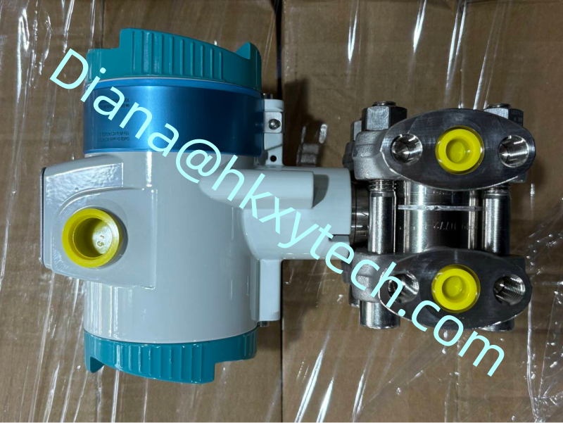
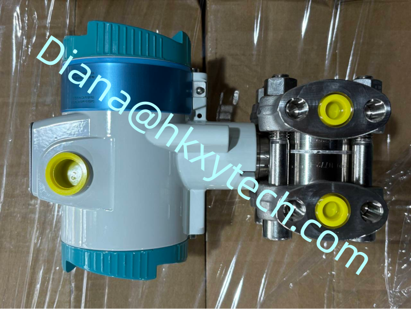
The SIEMENS 7MF0340-1GN01-5AF2-Z+A00+C11+C12+C20+E01+K84+Y01 must be accessible for proof testing without creating uncontrolled process risk. Design isolation and equalizing facilities, test connections and drainage so technicians can apply known pressure safely. Prevent bypass valves from being left in an unsafe position, and make bypass status visible to operations.
Phase 4: Validate the Cause and Effect
Verify the SIEMENS 7MF0340-1GN01-5AF2-Z+A00+C11+C12+C20+E01+K84+Y01 identity and approved range.
Apply pressure values below, near and above the trip point.
Confirm the logic solver sees the correct value and diagnostic state.
Prove the final action and alarm sequence using the approved test method.
Restore every bypass, valve and parameter to its authorized condition.
Phase 5: Plan Proof Tests and Change Control
A proof test for the SIEMENS 7MF0340-1GN01-5AF2-Z+A00+C11+C12+C20+E01+K84+Y01 should reveal dangerous failures that online diagnostics may not detect. The procedure must specify test equipment, applied points, acceptance limits, restoration steps and evidence retention. Record as-found data before adjustment; repeated drift can indicate a process or installation problem that a simple trim would conceal.
Safety reminder
Use the current Siemens safety manual and the project safety-requirement specification for the exact SIEMENS 7MF0340-1GN01-5AF2-Z+A00+C11+C12+C20+E01+K84+Y01 configuration. Product descriptions are not a substitute for the certified design basis.
Any change to the range, damping, fault response, impulse arrangement or proof-test interval must enter formal management of change. The SIEMENS 7MF0340-1GN01-5AF2-Z+A00+C11+C12+C20+E01+K84+Y01 supports a safety function only when the entire lifecycle remains controlled, tested and traceable.