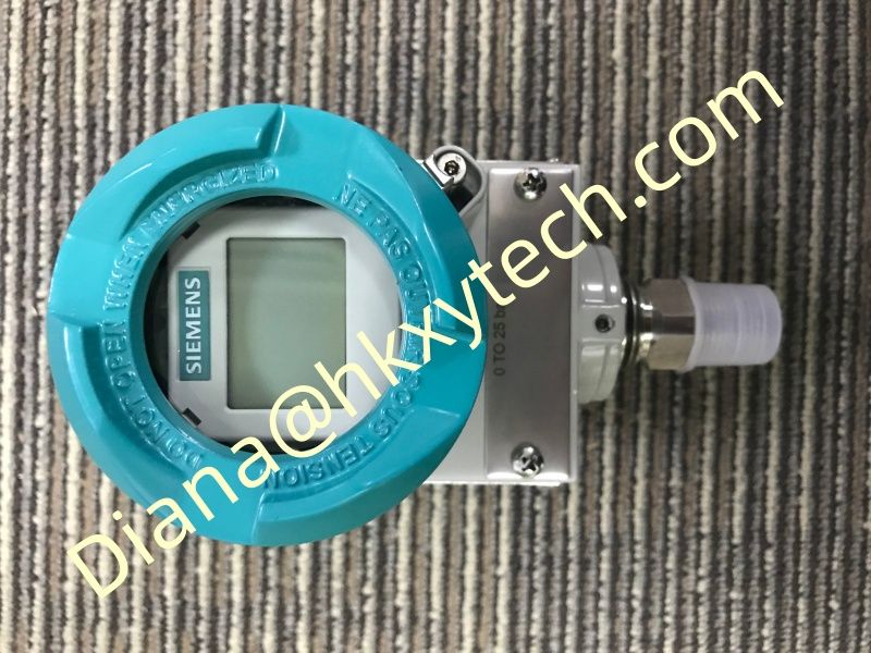
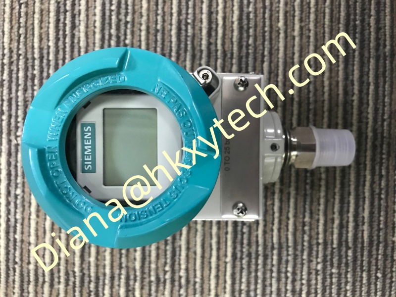
Protecting Low-Range Differential Pressure Accuracy with the SIEMENS 7MF0340-1GL01-5AF2-Z+A00+C11+C12+C14+E01+K84+Y01: Lessons from the Impulse Lines
Low differential pressure can reveal small changes in flow or equipment condition, but it also makes installation details unusually important. The SIEMENS 7MF0340-1GL01-5AF2-Z+A00+C11+C12+C14+E01+K84+Y01 may be capable of stable measurement while several millimetres of unequal liquid head, a small trapped bubble or a warm impulse line introduces an offset larger than the process signal.
A Practical Installation Story
Imagine the SIEMENS 7MF0340-1GL01-5AF2-Z+A00+C11+C12+C14+E01+K84+Y01 monitoring a clean-process filter. The transmitter is mounted neatly, the loop current is stable and the display responds. Yet the zero moves after every shutdown. The instrument is replaced, but the symptom returns. The actual cause is a pair of impulse lines with different slopes: one side retains liquid while the other drains.
The lesson is simple. Before commissioning the SIEMENS 7MF0340-1GL01-5AF2-Z+A00+C11+C12+C14+E01+K84+Y01, treat both pressure paths as part of the sensor. Match routing, length, bore and thermal exposure where practical. Keep liquid lines continuously sloped to avoid gas pockets and gas lines arranged to avoid liquid traps. When condensate pots are required, equalize their levels deliberately.
Build a Credible Zero
A zero check for the SIEMENS 7MF0340-1GL01-5AF2-Z+A00+C11+C12+C14+E01+K84+Y01 must have a defined physical condition. Safely equalize the high and low sides, wait for thermal and hydraulic stabilization, and record the manifold position. Do not perform an automatic zero trim while the process condition is uncertain. Otherwise the SIEMENS 7MF0340-1GL01-5AF2-Z+A00+C11+C12+C14+E01+K84+Y01 may be adjusted to compensate for an installation error that later changes.
Keep the Useful Signal Above the Noise
Review minimum, normal and maximum differential pressure instead of selecting only for the largest possible event. Set the calibrated range of the SIEMENS 7MF0340-1GL01-5AF2-Z+A00+C11+C12+C14+E01+K84+Y01 to cover credible operation and required upset conditions while retaining useful resolution. If the loop derives flow, remember that very low differential pressure represents an even smaller fraction of flow after square-root conversion.
Low-range field check
Equal impulse routing | No trapped phase | Stable temperature | Closed equalizer | Correct range | Verified square-root location
Prove Repeatability, Not One Lucky Point
Apply several small known differential-pressure points to the SIEMENS 7MF0340-1GL01-5AF2-Z+A00+C11+C12+C14+E01+K84+Y01 and approach them from both directions. Compare the local display, HART value and control-system indication. Repeat the zero check after restoring the manifold. Consistent results are more valuable than a single perfect reading.
Finally, capture the as-left range, damping, device tag and valve lineup. When the SIEMENS 7MF0340-1GL01-5AF2-Z+A00+C11+C12+C14+E01+K84+Y01 is installed with balanced pressure paths and a defensible zero, it can reveal real process changes without forcing operators to chase offsets created by the installation itself.