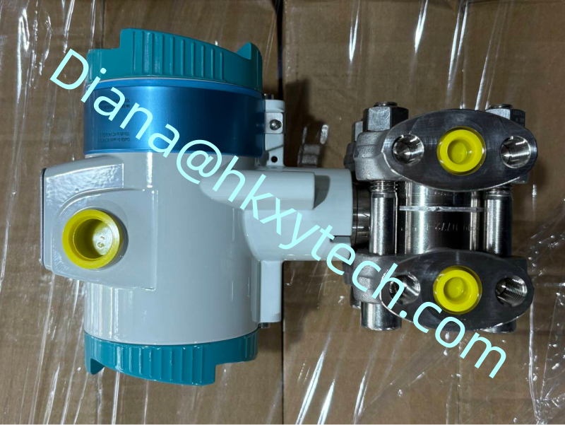
When a Differential Pressure Reading Looks Wrong: A Field Diagnostic Route for SIEMENS 7MF0340-1DL01-5AF2-Z+A00+C11+C12+C14+E01+K84+Y01
A drifting or implausible reading does not automatically mean that the SIEMENS 7MF0340-1DL01-5AF2-Z+A00+C11+C12+C14+E01+K84+Y01 has failed. Differential-pressure loops include process connections, impulse tubing, manifolds, condensate or gas pockets, electrical wiring and control-system scaling. A disciplined investigation separates these influences before anyone changes calibration or removes the transmitter.
Symptom: The Reading Is Fixed Near Zero
First confirm that the equalizing valve is closed and both isolation valves are open. An equalizer left open makes the SIEMENS 7MF0340-1DL01-5AF2-Z+A00+C11+C12+C14+E01+K84+Y01 see almost the same pressure on both sides. Next check for blocked root valves, plugged impulse lines or a process that is genuinely stopped. Compare the HART digital value with the analogue input; agreement suggests the issue is upstream of the control system.
Symptom: The Value Is Noisy
Observe whether noise follows pump speed, valve movement or electrical equipment. Process pulsation may require an installation or damping review, while electrical interference points toward cable routing, shielding or grounding. Do not increase damping on the SIEMENS 7MF0340-1DL01-5AF2-Z+A00+C11+C12+C14+E01+K84+Y01 until the source of the noise is understood, because excessive damping can hide a real process event.
Symptom: Zero Changes After Shutdown
Establish a valid zero before judging the SIEMENS 7MF0340-1DL01-5AF2-Z+A00+C11+C12+C14+E01+K84+Y01. Differential pressure is only zero when both sides are safely equalized under appropriate conditions. Liquid-head differences, unequal condensate legs and trapped gas can create a legitimate offset. Record valve positions and process conditions so the zero check can be repeated.
Symptom: Local and Control-Room Values Disagree
Confirm the range and units stored in the SIEMENS 7MF0340-1DL01-5AF2-Z+A00+C11+C12+C14+E01+K84+Y01.
Check whether square-root extraction is enabled in the transmitter, control system, both or neither.
Measure loop current and verify the analogue-input scaling.
Review fault-current behavior and any signal clamping.
If the HART value from the SIEMENS 7MF0340-1DL01-5AF2-Z+A00+C11+C12+C14+E01+K84+Y01 is correct but the displayed control-system value is wrong, investigate the loop configuration before recalibrating the sensor. If both are wrong under a known applied pressure, continue with a controlled pressure test.
Only Then Perform a Calibration Check
Isolate and equalize the SIEMENS 7MF0340-1DL01-5AF2-Z+A00+C11+C12+C14+E01+K84+Y01 using the approved procedure. Connect traceable test equipment with a suitable range and apply several increasing and decreasing points. Record as-found results before making an adjustment. A single zero correction cannot prove span performance or linearity.
After corrective work, restore the manifold carefully, check for leaks and prove the signal at the control system. The maintenance record for the SIEMENS 7MF0340-1DL01-5AF2-Z+A00+C11+C12+C14+E01+K84+Y01 should state the original symptom, confirmed cause, action taken and as-left evidence. This diagnostic route prevents unnecessary transmitter replacement and produces information that improves the next investigation.