Engineering the SIEMENS 7MF0340-1DM01-5BF2-Z+A00+C11+E20+K84+Y01 for repeatable measurement across process restrictions: Selection, Installation, Commissioning and Lifecycle Guidance
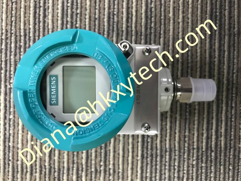
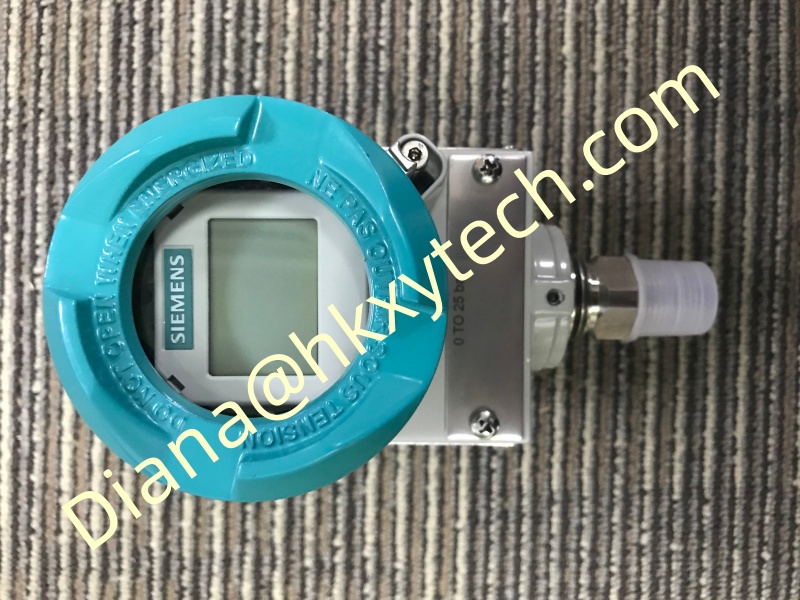
The SIEMENS 7MF0340-1DM01-5BF2-Z+A00+C11+E20+K84+Y01 is a SITRANS P320 transmitter ordered for Differential pressure and flow measurement. Its complete article number matters: every character and option suffix belongs to a defined factory configuration, so engineering, purchasing and maintenance teams should preserve the full SIEMENS 7MF0340-1DM01-5BF2-Z+A00+C11+E20+K84+Y01 code on drawings, quotations, inspection records and spare-parts lists.
For projects involving filter monitoring, primary flow elements and closed process lines, the SIEMENS 7MF0340-1DM01-5BF2-Z+A00+C11+E20+K84+Y01 provides a modern 4?0 mA HART measurement platform within the SITRANS P320 family. The exact pressure span, process connection, wetted materials, enclosure, display, approvals and certificates must be verified against the Siemens order data and the instrument nameplate before installation.
Start with the Measurement Duty
Define minimum, normal and maximum pressure, static line pressure, process temperature, ambient temperature and required response time before approving the SIEMENS 7MF0340-1DM01-5BF2-Z+A00+C11+E20+K84+Y01. For differential-pressure service, also document the high- and low-side conditions, expected differential span and maximum working pressure. For gauge-pressure service, confirm the reference condition and all credible overpressure events.
The selected range should place normal operation in a useful part of the calibrated span without sacrificing required turndown. A technically compatible transmitter can still deliver weak results when it is ranged too widely, installed on the wrong impulse connection or exposed to temperature conditions outside the intended design basis. Treat the SIEMENS 7MF0340-1DM01-5BF2-Z+A00+C11+E20+K84+Y01 order code and range sheet as controlled engineering data.
Electrical Integration and HART Communication
Check loop supply voltage, total cable resistance, barrier resistance and control-system input requirements as one circuit. Route the SIEMENS 7MF0340-1DM01-5BF2-Z+A00+C11+E20+K84+Y01 signal cable away from variable-frequency drive outputs and other high-energy conductors. Terminate shields according to the site grounding philosophy, seal every cable entry and preserve the ordered ingress protection.
Use HART communication to confirm device identity, range values, engineering units, damping, transfer function and diagnostics. The device tag in the SIEMENS 7MF0340-1DM01-5BF2-Z+A00+C11+E20+K84+Y01 should match the loop diagram and asset database. Archive the final parameter set so a future replacement can be commissioned from verified data instead of copied assumptions.
Order-Code and Replacement Control
Do not substitute a shortened family number for the SIEMENS 7MF0340-1DM01-5BF2-Z+A00+C11+E20+K84+Y01. Two SITRANS P320 transmitters may look alike while differing in sensor span, process materials, thread standard, housing, display, hazardous-area approval or documentation package. Compare every base-code character and every + option before accepting a replacement.
For quotation review, request confirmation of the complete SIEMENS 7MF0340-1DM01-5BF2-Z+A00+C11+E20+K84+Y01 configuration, current lifecycle status, calibration documentation and included accessories. Check whether a manifold, mounting bracket, cable gland, seal, remote seal or other project item is supplied separately. This prevents an apparently complete transmitter from arriving without the hardware needed for installation.
SIEMENS 7MF0340-1DM01-5BF2-Z+A00+C11+E20+K84+Y01 project check
Measurement: Differential pressure and flow
Application focus: repeatable measurement across process restrictions
Confirm before release: range, process connection, wetted materials, enclosure, approvals, option codes and documentation.
Commissioning Evidence, Not Just a Live Reading
Verify the full SIEMENS 7MF0340-1DM01-5BF2-Z+A00+C11+E20+K84+Y01 article number, nameplate range and process connection.
Inspect mounting, impulse lines, manifold position, grounding and cable sealing.
Equalize or vent the assembly safely and establish a valid zero reference.
Apply several known pressure points and compare local, HART and control-room values.
Prove alarm direction, loop scaling, fault current and any square-root flow configuration.
Record as-left values, device revision and configuration files for the SIEMENS 7MF0340-1DM01-5BF2-Z+A00+C11+E20+K84+Y01.
Mechanical Installation That Protects Accuracy
Mount the SIEMENS 7MF0340-1DM01-5BF2-Z+A00+C11+E20+K84+Y01 where vibration, radiant heat, water ingress and maintenance access can be managed. Support impulse tubing independently and avoid using the transmitter body to correct pipe misalignment. For liquid service, route lines to prevent trapped gas; for gas service, prevent liquid pockets; and for steam service, use the approved condensate arrangement with equalized legs.
Confirm manifold orientation, pressure-side identification and vent or drain access before tightening the installation. Open isolation valves in a controlled sequence and never apply one-sided pressure beyond the allowable limit. A stable bracket, short impulse paths and disciplined leak testing help the SIEMENS 7MF0340-1DM01-5BF2-Z+A00+C11+E20+K84+Y01 reproduce the process condition rather than installation-induced disturbances.
Lifecycle Checks for Consistent Performance
Inspect the SIEMENS 7MF0340-1DM01-5BF2-Z+A00+C11+E20+K84+Y01 at intervals based on service severity. Look for blocked impulse lines, leaking fittings, manifold errors, moisture, corrosion, damaged cable entries and unexplained zero movement. Compare diagnostics with process history before changing calibration; many apparent transmitter faults originate in the pressure path.
After maintenance, restore every valve to its documented operating position, check loop response and update the service record. Retain the original SIEMENS 7MF0340-1DM01-5BF2-Z+A00+C11+E20+K84+Y01 order code and as-left configuration so future troubleshooting can distinguish a process change from an instrument change.
Where This Configuration Adds Value
The SIEMENS 7MF0340-1DM01-5BF2-Z+A00+C11+E20+K84+Y01 is suited to filter monitoring, primary flow elements and closed process lines when its ordered range, wetted materials and approvals match the service. Typical engineering objectives include stable control feedback, filter-condition monitoring, flow calculation, equipment protection, energy accounting and clearer maintenance diagnostics.
Good results depend on the complete measurement chain. Primary elements, impulse lines, manifolds, wiring, control-system scaling and operating procedures all influence the final value. Selecting the SIEMENS 7MF0340-1DM01-5BF2-Z+A00+C11+E20+K84+Y01 is therefore one part of a loop design, not a substitute for loop engineering.
Engineering Summary
The robust SIEMENS 7MF0340-1DM01-5BF2-Z+A00+C11+E20+K84+Y01 brings the SITRANS P320 platform to repeatable measurement across process restrictions. Preserve the exact configuration, validate the complete loop and keep commissioning evidence with the asset record. With those controls in place, the SIEMENS 7MF0340-1DM01-5BF2-Z+A00+C11+E20+K84+Y01 can support dependable measurement and efficient lifecycle maintenance.