
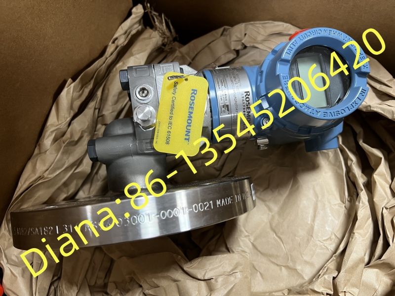
Matching Rosemount 5408A1SFA1I11R4ABCAA3M5Q4 to the Nozzle, Process Connection and Real Operating Level Range
Rosemount 5408A1SFA1I11R4ABCAA3M5Q4 is a configured two-wire radar level transmitter, but the transmitter alone does not determine whether an installation will perform well. The vessel nozzle, process connection, antenna exposure and available free space must agree with the exact ordered construction. A disciplined mechanical review prevents many commissioning problems before the instrument reaches site.
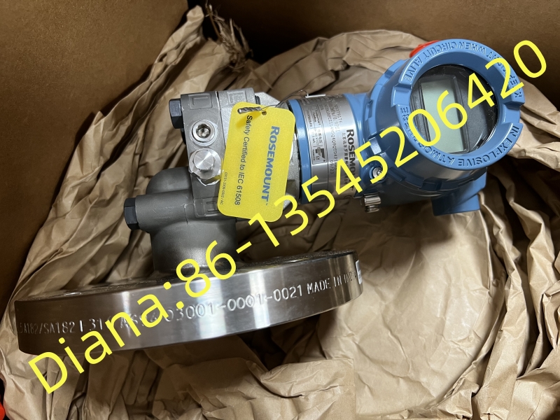
Treat the nozzle as part of the measuring system
Measure the nozzle inside diameter, height, flange rating and internal surface condition. Confirm whether the antenna projects below the nozzle and whether any reducer, weld bead or extension creates a restricted path. A drawing with actual dimensions is more reliable than choosing a radar only from a previous tag number.
Check clearance from the vessel wall, ladders, coils, mixers and the inlet stream. The preferred location gives the Rosemount 5408A1SFA1I11R4ABCAA3M5Q4 a stable view of the product surface through all normal levels. If the process contains heavy condensation or coating material, include inspection access and cleaning practice in the design.
Confirm materials and ratings against the process
Compare the exact process connection, pressure rating, temperature range and exposed materials with the piping or vessel specification. The complete model suffix must be checked against the Rosemount ordering information rather than decoded from appearance. Hazardous-area approval, cable entry and enclosure requirements should match the site classification and wiring method.
For aggressive or high-temperature service, review gasket selection and any temperature limits created by the connection arrangement. Mechanical compatibility should be approved before shipment because adapters introduced later can change the antenna position and echo environment.
Scale the output from verified vessel references
Establish the measurement reference point and tank height from approved drawings. Configure lower and upper range values so the 4–20 mA signal represents the intended process window. If the control system calculates volume or mass, confirm the strapping table, density source and scaling location to prevent duplicate conversion.
During loop testing, compare the local display, digital variable, analog current and control-system indication. Verify alarm direction and failure current. Record the configured damping because excessive damping can delay control response, while too little damping may pass normal surface movement into the process loop.
Prepare a replacement request that can be audited
State Rosemount 5408A1SFA1I11R4ABCAA3M5Q4 in full and attach the existing nameplate, instrument datasheet and nozzle drawing. Ask the supplier to confirm any deviation in writing. A technically complete inquiry should also identify the process medium, operating limits, output protocol, approvals and required documentation.
At receiving inspection, compare the delivered code and connection with the purchase order before installation. Keeping the quotation, order acknowledgement, device serial number and final configuration together reduces the risk of an apparently similar but unsuitable unit being placed into service.

