Applying the ABB LMT200.Y0.S6.R1.B1.D1.L2.H1.M5.R3 for Accurate, Non-Intrusive Level Measurement on Process Vessels
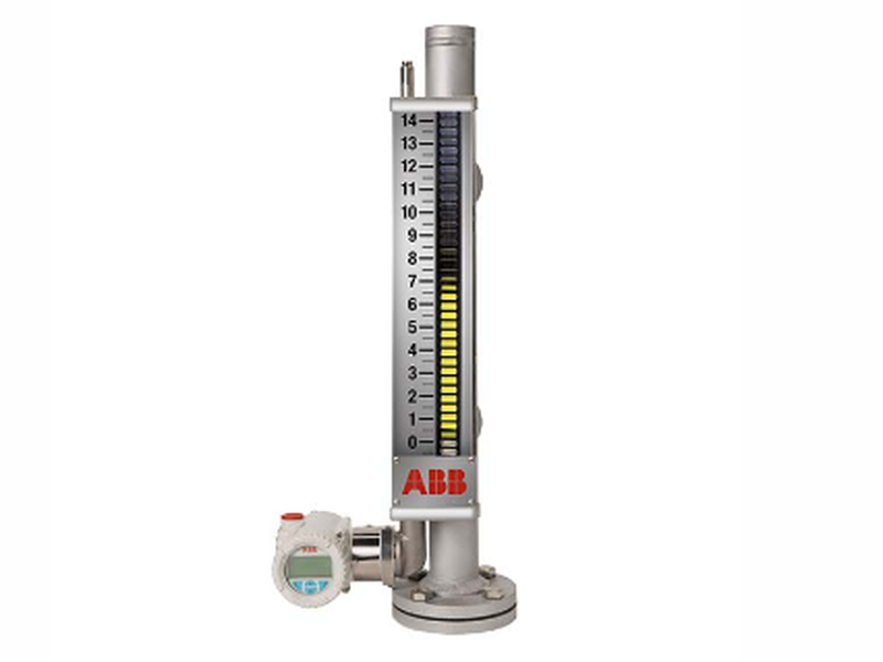
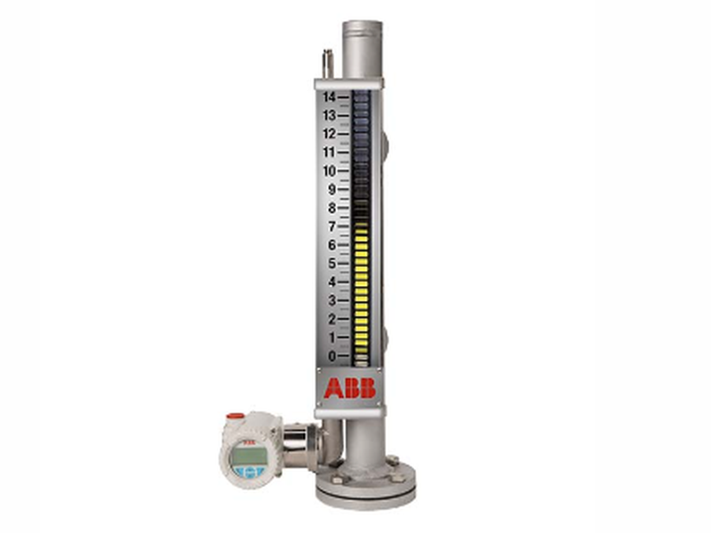
The ABB LMT200.Y0.S6.R1.B1.D1.L2.H1.M5.R3 is an external-mount magnetostrictive level transmitter intended to work beside a compatible magnetic level gauge. It follows the gauge float without penetrating the vessel, turning float position into a continuous electronic level signal while preserving direct local indication. This arrangement is valuable where operators want dependable measurement, straightforward maintenance and less disturbance to the process connection.
What this configured LMT200 contributes to a level-measurement loop
ABB designed the LMT200 family for total-level or interface duties in demanding storage and process applications. The sensor reads the magnetic float position, and the loop-powered electronics provide a usable plant signal without requiring the sensing element to enter the vessel. The family supports local HMI indication, waveform viewing and NAMUR NE107 diagnostic messaging, helping technicians separate a process issue from a wiring, setup or device-health issue.
| Selection detail | Project information |
|---|---|
| Model | ABB LMT200.Y0.S6.R1.B1.D1.L2.H1.M5.R3 |
| Instrument type | External-mount magnetostrictive level transmitter |
| Typical measurement | Continuous total level or interface level with a compatible magnetic level gauge |
| Family accuracy | 0.01% of full scale or ±1.27 mm, whichever is greater |
| Family probe length capability | Up to 15 m / 50 ft, subject to the selected configuration |
| Ordering-code review | Confirm every suffix, measuring length, approvals, output and mounting arrangement against the project datasheet |
Installation planning should begin at the magnetic gauge
The mechanical relationship between the ABB LMT200.Y0.S6.R1.B1.D1.L2.H1.M5.R3 and the float chamber determines the quality of the measurement. Confirm the active measuring span, upper and lower dead zones, float type, chamber orientation and mounting clearances before work starts. The transmitter housing can be oriented for practical viewing and cable access, but the sensor must remain correctly positioned along the float travel.
Loop design should also cover supply voltage at the terminals, cable shielding, grounding practice and the input characteristics of the control system. Where HART communication is used, retain the required loop resistance and document the device tag, range values, damping and alarm behavior. Hazardous-area projects require verification of the exact approval code and installation drawing rather than relying on the general LMT200 family description.
Commissioning and lifecycle checks
During commissioning, compare the local indication with a known physical reference at more than one level. Verify lower and upper range values, output direction and the response to float movement. Record the full model string ABB LMT200.Y0.S6.R1.B1.D1.L2.H1.M5.R3, serial number and configured measuring length in the instrument database so future replacements can be matched accurately.
Routine maintenance can focus on gauge condition, float freedom, cable integrity and diagnostic messages because the external sensor design avoids opening the vessel for normal electronic service. If readings become unstable, inspect the chamber and float before changing calibration. Matching the delivered ABB LMT200 configuration to the approved datasheet remains the most reliable way to preserve measurement performance through the plant lifecycle.