Coordinating Redundant Power, ESB Connections and the Installed I/O Population When Procuring Yokogawa SNB10D-415/CU2N for a Safety System Node
Yokogawa SNB10D-415/CU2N is a rack-mount safety node unit reference. The SNB10D provides an interface between field I/O and the safety control unit through an ESB bus and supplies power to installed I/O modules. The ordering suffix identifies a particular power and connector arrangement that should remain intact in the purchase request.
Redundancy needs both supply paths
For Yokogawa SNB10D-415/CU2N, identify the intended incoming supply arrangements and their connection to the existing cabinet design. The redundant-power designation describes a hardware arrangement, not proof that the site has two independent sources.
A connector and a terminator are distinct
The /CU2N option associated with Yokogawa SNB10D-415/CU2N identifies the connector unit. The separate /CU2T option includes termination and should not be substituted without checking the ESB layout. Preserve the bus drawing and the node position in that layout. The receiving checklist for Yokogawa SNB10D-415/CU2N should include the specified connector arrangement so a small accessory difference does not become a commissioning delay.
| Ordering reference | Yokogawa SNB10D-415/CU2N |
|---|---|
| Device | SNB10D rack-mount safety node unit |
| Suffix -4 | Dual-redundant power supply; R4.01 or later context |
| Supply code 1 | 100 to 120 V AC |
| Environmental code 5 | ISA G3; -20 to 70 C; without explosion protection |
| Option /CU2N | ESB connector unit S9342FA |
| Different option | /CU2T includes a terminator; not an automatic substitute |
The rack has a population
- Record the installed module population around Yokogawa SNB10D-415/CU2N, including power supplies, bus interfaces and field I/O. Mark which modules remain in service and which are part of the new order.
- A quotation for Yokogawa SNB10D-415/CU2N should distinguish the node assembly from a fully populated rack. Photographs can help describe the existing system, but the agreed bill of materials determines what the supplier must deliver.
Keep system compatibility visible
- When assessing Yokogawa SNB10D-415/CU2N, identify the safety-system release and applicable hardware requirements. The responsible system engineer should review any proposed revision or alternate assembly against the installed architecture.
- Purchasing Yokogawa SNB10D-415/CU2N does not authorize an unplanned change to a safety application. The agreed maintenance scope and system verification process should accompany the hardware request through installation and return to service.
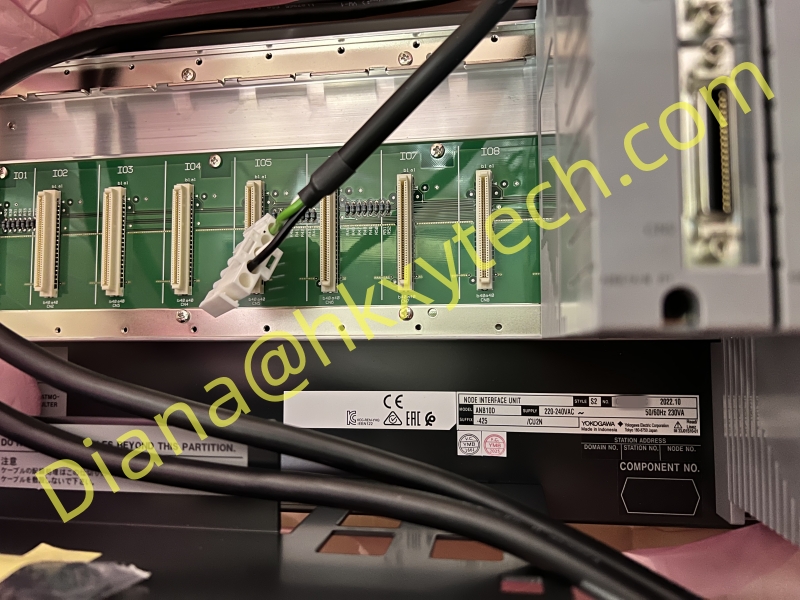
Shared reference image for Yokogawa SNB10D-415/CU2N. The supplied list associates this brand stock image with the request; it is not a photograph confirming the exact model, configuration or accessories offered.
Check the supply voltage on receipt
Compare the supplied suffix of Yokogawa SNB10D-415/CU2N with the actual voltage requirement before installation. A nearby SNB10D variant can use a different supply while retaining a similar rack appearance.
Deliver a node that can be checked
An order for Yokogawa SNB10D-415/CU2N should preserve the complete suffix, intended module scope, condition and available documentation. Compare the delivered labels and included connector unit with the approved offer. Keep receiving evidence with the rack record. Future requests for Yokogawa SNB10D-415/CU2N can then identify the accepted assembly and installed context without mistaking a generic node image for a complete specification.