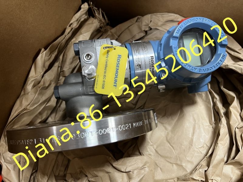
Selection, Installation and Commissioning Guide for Rosemount 3051CD2F02A1BH2I1Q4Q32 Differential Pressure Transmitter
Rosemount 3051CD2F02A1BH2I1Q4Q32 is a configured differential pressure transmitter for industrial process measurement. Buyers should retain the complete model code and confirm the calibrated range, process connection and ordered options before replacement.

Identify the measurement duty before decoding options
Rosemount 3051CD2F02A1BH2I1Q4Q32 is a configured coplanar differential pressure transmitter. The sensing principle supports differential-pressure measurement and can be applied to flow, level, filter monitoring and other duties when the surrounding process hardware is engineered correctly. The transmitter measures pressure difference; the control system or configured device then relates that measurement to the required process variable.
Begin a replacement review with the instrument index and loop drawing. Record the measured variable, lower and upper range values, engineering units, normal operating point, maximum static pressure, process temperature and expected upset conditions. These application values are more important than choosing a transmitter solely because the front portion of the model number matches.
Understand the significance of the CD2 sensor range
In the Rosemount 3051 ordering structure, CD identifies a differential pressure transmitter and the 2 designates the applicable sensor range. Current manufacturer data lists a range-2 upper and lower sensor limit of plus or minus 250 inH2O, approximately plus or minus 621.6 mbar, with a published minimum span that depends on the current product revision. This is a sensor capability, not automatically the calibrated operating range of the delivered unit.
The accepted quotation should state the required calibrated lower and upper range values and the desired output behavior. Avoid using the maximum sensor limit as the working span unless the process design actually calls for it. A suitable calibrated range places normal operation where measurement resolution and diagnostic information remain useful.
Preserve the complete configuration code
The characters after 3051CD2 define construction and option choices such as output protocol, process interface, materials, approvals and additional features. Because several options can look similar after installation, retain the complete 3051CD2F02A1BH2I1Q4Q32 code on the request, purchase order, receiving inspection and asset record.
Compare the existing nameplate with the approved instrument data sheet instead of decoding uncertain suffixes from memory. If a supplier proposes a substitute, request a line-by-line configuration comparison. Pay particular attention to wetted materials, flange or manifold compatibility, hazardous-area certification, housing entry, display, transient protection and any calibration or quality documentation required by the project.
Engineer the process connection and manifold as one assembly
A differential pressure transmitter depends on both high- and low-pressure process connections. Confirm the coplanar flange, manifold type, bolt material, gasket or O-ring selection and pressure rating. For flow service, verify compatibility with the primary element and impulse-line arrangement. For level service, review tap elevations, wet-leg or dry-leg design, fluid density and the effect of remote seals if present.
Support impulse tubing so the transmitter is not carrying piping loads. Route lines to avoid unintended gas pockets in liquid service and liquid pockets in gas service, and provide the slope and vent or drain points required by the engineering standard. Equal high- and low-side conditions during zero checks must be created safely through the approved manifold procedure.
Protect measurement quality during installation
Choose a mounting location that limits vibration, extreme ambient temperature and direct exposure to damaging process conditions while keeping the transmitter accessible. The housing should be oriented so displays and terminals can be reached without stressing conduit or impulse tubing. Seal cable entries and maintain the enclosure rating specified for the site.
Before applying process pressure, confirm manifold valve positions, tubing identification and pressure rating. Introduce pressure gradually and check every joint for leakage. Never use the transmitter body to pull misaligned tubing into place. An installation that places permanent stress on the process interface can create leaks or zero shifts and can complicate future removal.
Check the 4-20 mA HART loop as an electrical system
The full model indicates a configured electronic output, and the project documentation should confirm the intended 4-20 mA HART arrangement. Verify loop supply voltage, total resistance, polarity, grounding and the control-system input. HART communication requires adequate loop impedance and a compatible communicator or host. Intrinsically safe loops also require the specified barriers and entity-parameter review.
Route signal wiring separately from high-power cables and preserve shield continuity according to the site standard. Check the configured device tag, units, range, damping, alarm direction and output limits before connecting the loop to automatic control. Record the final configuration so later troubleshooting does not depend on undocumented field changes.
Commission zero, range and application scaling carefully
A zero adjustment should only be performed under a verified equal-pressure condition that is valid for the installation. For level applications, an installed zero can include elevation or suppression effects and should follow the project calculation. For flow applications, verify the square-root relationship and scaling location so the transmitter and control system do not both apply the same conversion.
Compare the transmitter reading, analog output and control-system value at several points. Where project procedures require calibration, use traceable pressure equipment with suitable accuracy. Document as-found and as-left data, test equipment, environmental conditions and any configuration changes. This record is essential when diagnosing later drift or impulse-line problems.
Separate transmitter faults from process-connection problems
Unstable or slow differential-pressure readings can result from plugged impulse lines, leaks, trapped gas or liquid, manifold leakage, temperature effects, vibration or a changing process. Inspect the entire measurement path before replacing the electronics. A transmitter may be operating correctly while the pressure presented to its two sensing ports is no longer representative.
Routine maintenance should include visual inspection, enclosure checks, loop diagnostics, comparison with process expectations and the plant calibration interval. Preserve the configuration and calibration record before replacement. If the process contains hazardous, hot or toxic material, isolate, depressurize and drain or vent the connection under the approved safety procedure.
Prepare a quotation that can be technically evaluated
State Rosemount 3051CD2F02A1BH2I1Q4Q32 in full and attach the instrument data sheet. Include calibrated range, units, static pressure, process temperature, wetted-material requirements, process flange or manifold, housing entry, display, communication protocol, approvals, mounting accessories and documentation. Identify whether the supplier must configure the tag, range and alarm behavior before shipment.
Ask the supplier to confirm the exact model code and clearly identify any deviation. For a replacement, provide the existing serial number and photographs of the nameplate and process assembly. These details allow the buyer, instrument engineer and maintenance team to review one consistent technical package before the order is released.
Manufacturer reference for the Rosemount 3051 pressure transmitter family