
ABB 266DSHGSSA2A1L1B1I1C1 High-Performance Differential Pressure Transmitter for Flow, Level and Industrial Process Pressure Measurement
 October
16, 2026
Select ABB 266DSHGSSA2A1L1B1I1C1 for Stable Differential Pressure, Flow and Level Measurement with Practical Field Diagnostics and Configuration Support
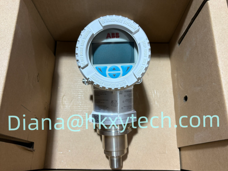
ABB 266DSHGSSA2A1L1B1I1C1 is a configured 266DSH differential pressure transmitter for demanding process measurement. The standard DP-style design can support differential pressure monitoring as well as flow, level, filter-condition and related applications when it is paired with the correct primary element, manifold and impulse-line arrangement. Long-term stability and configurable electronics make the platform suitable for both new installations and replacement projects.
Four common measurement duties for the ABB 266DSH
Flow measurement: detects pressure drop across a compatible orifice plate, venturi, nozzle or other primary element.
Tank level: measures hydrostatic differential pressure in open or pressurized vessels using the appropriate wet-leg or dry-leg arrangement.
Filter and equipment monitoring: tracks differential pressure across filters, strainers, exchangers or other process equipment.
Process-pressure comparison: monitors the difference between two process points where stable and repeatable measurement is required.
Performance and maintenance features across the 266DSH family
ABB publishes base accuracy from ±0.06% for the 266DSH family, with sensor spans covering a wide range of differential-pressure duties. Communication alternatives include HART, PROFIBUS PA and FOUNDATION Fieldbus, depending on configuration. The platform also offers an in-field replaceable electronics module, auto-configuration support and local display options. Through-the-glass operation can allow authorized setup without removing the windowed cover on compatible versions.
Build the measurement around the actual process conditions
Do not select the transmitter by maximum family range alone. Record normal and maximum differential pressure, static line pressure, process and ambient temperature, process medium, density, required turndown, response time and expected overpressure. For flow, retain the primary-element calculation and square-root extraction details. For level, document the tapping elevations, vessel pressure, leg arrangement and density conditions used for calibration.
Configuration points hidden inside the full order code
Sensor range and maximum working-pressure construction.
Diaphragm, process-flange, O-ring, drain and vent materials.
Process-connection orientation and adapter arrangement.
Housing, cable entry, display, output protocol and local configuration features.
Hazardous-area, functional-safety, marine or other project certifications.
Use 266DSHGSSA2A1L1B1I1C1 exactly as shown on the inquiry and ask the supplier to identify any difference in the offered configuration. A family-compatible transmitter can still be unsuitable if its pressure range, materials, flange orientation or approval differs from the installed unit.
Installation and loop-verification priorities
Mount the transmitter and manifold so the high- and low-pressure sides remain correctly identified. Route impulse lines to suit liquid, gas or steam service and remove trapped gas or liquid as required by the application. During commissioning, confirm leak tightness, zero, calibrated range, damping, transfer function, alarm behavior, tag and output scaling. Complete a loop test to the control system and preserve the final configuration in the maintenance record.