
Yokogawa ANB10D-425/CU2N Dual-Redundant ESB Bus Node Unit for CENTUM Expansion, Retrofit and Spare Planning
 September
08, 2026
September
08, 2026
Reading the complete Yokogawa ANB10D-425/CU2N configuration before adding or replacing an ESB Bus node in a CENTUM control system
Yokogawa ANB10D-425/CU2N is not simply an empty rack identified by an ANB10D family label. Its complete suffix specifies a dual-redundant ESB Bus node-unit arrangement, a particular AC supply range, the basic non-explosion-protection construction and a two-connector ESB Bus option. Those details matter when a CENTUM maintenance team is replacing an installed node, adding remote I/O capacity or preparing a shutdown spare.
The node unit sits between field I/O and the Field Control Unit. Yokogawa describes the ESB Bus Node Unit as providing the interface that communicates analog and contact I/O signals to the FCU through the ESB bus while also supplying power to the installed I/O modules. A compatible result therefore depends on the node code, power modules, SB401 interface modules, I/O allocation, FCU-side coupler, ESB Bus cables and project database working as one system.
For a buyer, the strongest inquiry starts with Yokogawa ANB10D-425/CU2N exactly as written and then adds the installed-system evidence. For an engineer, the same code becomes a checklist: dual redundancy must be preserved, 220-240 V AC must suit the cabinet supply, the non-explosion-protection construction must be acceptable for the installation area, and the connector option must match the bus topology.
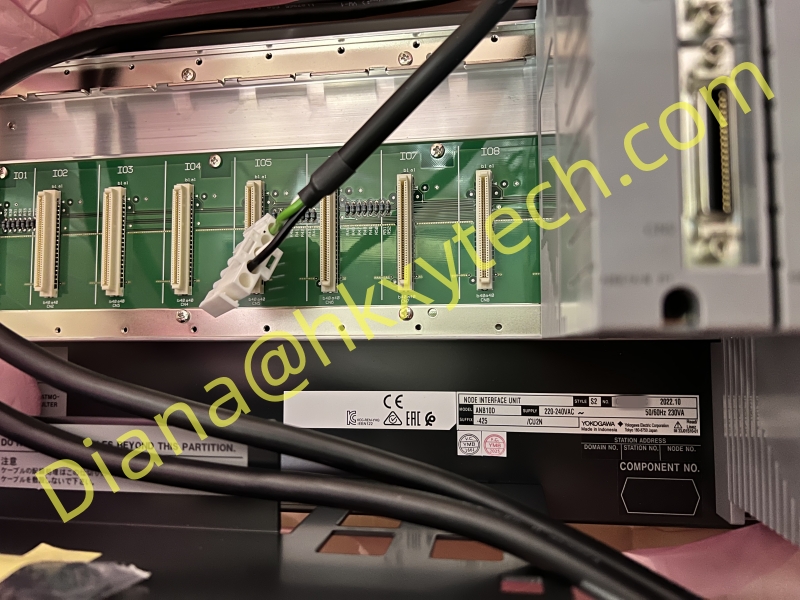
Reference image for Yokogawa ANB10D-425/CU2N. Confirm the complete order code, power-input label, installed modules and connector-unit scope against the offered equipment.
The order code defines the supply boundary
The following breakdown is based on Yokogawa General Specification GS 33K50F20-50E. It turns the model string into an auditable purchasing description. It should still be checked against the latest official document revision and the nameplate of the offered unit because complete cabinet scope, installed I/O modules and project-specific accessories may be quoted separately.
| Code element | Published meaning | Buyer verification |
| ANB10D | Node Unit for Dual-Redundant ESB Bus | Confirm that the requirement is the ANB10D dual-redundant node, not the ANB10S single-ESB-Bus family or the ANB11D optical-repeater node. |
| -4 | Dual-redundant power supply configuration | Check that two correct power-supply modules and the intended redundancy arrangement are included in the quoted scope. |
| 2 | 220-240 V AC power supply, 50/60 Hz | Verify cabinet voltage, upstream protection, terminal condition and the exact power-module labels before energizing. |
| 5 | Basic type with no explosion protection | Confirm the cabinet location and site classification. Do not treat this suffix as an explosion-protected configuration. |
| /CU2N | Connector Unit for ESB Bus, part S9562FA, two pieces | Confirm both connector units are included and determine separately whether the last node requires the terminator-equipped /CU2T arrangement. |
This is why shortening Yokogawa ANB10D-425/CU2N to ANB10D can create an expensive mismatch. Nearby suffixes alter the supply voltage, environmental support, explosion-protection basis or connector-unit selection. A photograph may establish the product family, but only the complete code and physical labels define the requested configuration.
Discrete input module Yokogawa ADV169-P00
Yokogawa ADV569-P00 digital output module
Ethernet communication module ALE111-S50 Yokogawa
Yokogawa Relay output module Yokogawa MRO-32/24VDC-230VAC/DPS with installed RELPOL relays
Yokogawa ANB10D-425/CU2N Expansion Unit for Redundant ESB, 19" Rack Mount
Yokogawa ESB ANB10D-425/CU2T Redundant Bus Expansion Unit, 19" Rack Mount
Bus connection module ESB EC402-50 Yokogawa
Terminal panel Yokogawa MRIC-32/230VAC-DC interface module
Yokogawa Expansion unit for redundant ESB bus ANB11D-B25/BU2A
Yokogawa AAI143-H50/A4S10 analog input module, 16 isolated channels, 4-20mA
Yokogawa ESB Main Optical Repeater Module for 5 km (for N-IO/FIO) ANT401-5E/CU1T
Yokogawa Analog output module art. AAI543-H50/A4S10
Yokogawa Signal cable (50-50 pins) KS10-10
Yokogawa ALP121-S00 profibus module
Yokogawa Duplicated control unit (for Vnet/IP and FIO, mounted in a 19" rack) ref. AFV30D-A41252
What belongs inside the node, and what may not be included
The documented dual-redundant arrangement uses two power-supply modules and two SB401 ESB Bus Interface Slave Modules. The node supports up to eight I/O modules, although allocation rules, environmental limits and the selected FIO modules must be reviewed for the actual project. Yokogawa also notes that modules with built-in barriers require an insulating partition in the specified position.
A quotation for Yokogawa ANB10D-425/CU2N should therefore separate the base node configuration from optional or already-installed modules. Ask whether the offer includes the PW482 power supplies appropriate to the 220-240 V AC code, two SB401 modules, blank covers, mounting accessories, bus connector units, I/O modules and any insulating partition. Do not assume a photographed populated rack and an offered base assembly have the same scope.
Dual-redundant power path: two compatible power-supply modules are expected for the -4 arrangement.
Dual-redundant ESB Bus interface: two SB401 modules form the documented redundant interface arrangement.
I/O capacity: up to eight I/O modules, subject to module allocation and installation restrictions.
Rack installation: 19-inch rack mounting using four M5 fixing points in the documented mechanical arrangement.
Published loaded weight reference: approximately 10 kg when fitted with eight I/O modules.
220-240 V AC published consumption reference: 230 VA and 120 W for the node-unit specification; final cabinet design must use the current approved document.
The term node unit can describe different commercial scopes in secondary-market listings. For Yokogawa ANB10D-425/CU2N, the purchase order should name every required module and accessory, state whether used or refurbished material is acceptable and define the functional test expected before shipment.
Follow the two ESB paths from the FCU to the connector units
Dual redundancy is an architecture, not a label. At the FCU, the ESB Bus connection uses EC401 or EC402 coupler modules according to the supported control-station arrangement. At the node, SB401 interface modules and the two /CU2N connector units participate in the redundant Bus1 and Bus2 paths. Dedicated YCB301 ESB Bus cable is identified in Yokogawa system documentation.
When Yokogawa ANB10D-425/CU2N is added in a chain, the engineering team must determine whether another node follows it. A normal connector passes the bus onward, while the last node needs the termination strategy defined by the design. The /CU2N option is the non-terminator connector-unit selection; /CU2T is the separate option with terminator-equipped connector units. The required choice comes from topology, not from visual preference.
Modern Yokogawa system guidance describes the ESB bus as dual redundant, operating at 128 Mbps with dedicated cable, allowing up to eight ANB10D/ANB11D node units per FCU in the referenced N-IO/FIO architecture. It also gives up to two star lines, up to eight chain hops and a documented 10 m distance condition for the relevant EC401/EC402 arrangement. These system-level limits must be reconciled with the exact CENTUM release and installed FCU rather than copied blindly into a legacy expansion.
A replacement review should begin at the cabinet, not at the supplier listing
Before removing the existing node, photograph the complete rack, every front label, both power entries, SB401 positions, I/O module order and both ESB Bus paths. Export or record the project database assignment and mark each field cable. If the replacement is driven by a fault, capture alarms and diagnostic behavior before power is removed. That information is difficult to recreate after the node is disconnected.
Verify the full installed code and compare it character by character with Yokogawa ANB10D-425/CU2N.
Confirm 220-240 V AC, protective devices, grounding, isolation and the condition of both redundant supply paths.
Record the part numbers and revisions of both power modules, both SB401 modules and all installed I/O modules.
Trace Bus1 and Bus2 from the FCU couplers through the /CU2N connectors and determine where termination is provided.
Review rack space, airflow, ambient conditions, barrier-module partition requirements and cable access before fitting the replacement.
Back up the control-system database, define rollback criteria and schedule loop checks for every affected I/O channel.
After energizing, prove both redundant power paths and both ESB Bus paths independently, then verify normal operation after failover recovery.
This sequence prevents a common procurement error: accepting Yokogawa ANB10D-425/CU2N as physically correct while leaving the actual redundancy, termination or module population unverified. The acceptance test should demonstrate the required system behavior, not merely show that the rack powers up.
Five questions that expose hidden quotation differences
Does the offer include a complete dual-redundant node or only the base unit and mechanical frame?
Are the two power-supply modules correct for 220-240 V AC, and are their revisions compatible with the installed system?
Are two SB401 modules present, and has communication through both redundant paths been functionally tested?
Are two S9562FA connector units included for /CU2N, and is termination handled elsewhere in the site topology?
Which I/O modules, dummy covers, mounting parts and partitions are included, excluded or shown only in the reference photograph?
Condition also needs a written definition. New surplus, unused old stock, refurbished and removed-from-service equipment are not interchangeable descriptions. For any non-factory-new Yokogawa ANB10D-425/CU2N, request serial-number photographs, storage history, inspection details, test results, warranty terms and return conditions.
Where this node-unit configuration is normally considered
Yokogawa ANB10D-425/CU2N may be considered in process plants that use CENTUM and FIO architectures for distributed analog and contact I/O. Typical sourcing scenarios include a brownfield control-system extension, replacement after cabinet damage, restoration of redundant power or bus capability, construction of a strategic spare and migration work where the original node must remain available during a staged transition.
The strongest fit is determined by the installed architecture rather than the industry name. Oil and gas, refining, chemical, power, water, metals and other continuous-process facilities may all use similar node concepts, but their I/O module mix, cabinet environment, shutdown policy and certification requirements differ. The destination project must approve the exact configuration.
If the site already operates an ANB10D node, the fastest technical review is usually a side-by-side comparison of nameplates, module population and drawings. If the requirement is a new extension, the FCU capacity, software license, supported CENTUM release, bus topology, cable distance and database engineering should be confirmed before hardware is purchased.
Search intent and inquiry language for an exact-code purchase
Industrial buyers may search for a Yokogawa dual-redundant ESB Bus node unit, ANB10D 220-240 V AC rack, CENTUM FIO remote I/O node, SB401 node assembly, S9562FA connector-unit package or Yokogawa ANB10D replacement. These phrases describe the use case, while Yokogawa ANB10D-425/CU2N remains the controlled order reference that ties the page to one configuration.
A useful inquiry should include quantity, destination country, required delivery date, full nameplate photographs, existing FCU model, CENTUM release, EC401/EC402 arrangement, SB401 revisions, I/O module list, supply voltage, Bus1/Bus2 cable routing and connector/termination details. State whether the requirement is for a complete populated assembly, a base node, individual spares or engineering review.
HKXY Tech presents Yokogawa ANB10D-425/CU2N as an exact-code sourcing reference for maintenance, expansion and retrofit planning. Availability, included modules, manufacturing status, condition and regulatory suitability must be confirmed in the current offer. The supplied image supports family recognition but does not replace the delivered nameplate or approved Yokogawa documentation.
A practical acceptance statement for the purchase order
The purchase line should retain Yokogawa ANB10D-425/CU2N without abbreviation and then list the agreed supply boundary. Require two correct AC power modules, two SB401 modules and two S9562FA connector units only when those items form part of the approved offer. List every included I/O module separately by model and revision, and identify any parts reused from the existing cabinet.
Final acceptance should cover physical condition, code and serial traceability, power-up checks, both redundant power paths, both ESB Bus communication paths, connector-unit scope and loop-level operation after installation. This keeps the commercial description aligned with the engineering outcome and makes future maintenance records more reliable.
Manufacturer references used for this page: Yokogawa GS 33K50F20-50E for ANB10S/ANB10D ESB Bus Node Units and Yokogawa GS 33J62A10-01EN for the N-IO/FIO system and ESB Bus architecture. Verify the latest document revision and project-specific compatibility before order approval.