
High-Reserve ABB 1SVR360563R1001 CP-C.1 24 VDC 5 A Industrial Power Supply for Stable Automation Panels and Scalable Control Loads
 August
20, 2026
August
20, 2026
Sizing and Commissioning the ABB 1SVR360563R1001 CP-C.1 Power Supply: A Practical 24 VDC Capacity and Reliability Guide
The ABB 1SVR360563R1001 is the CP-C.1 24/5.0 primary switch-mode power supply designed to convert a broad AC or DC input into a regulated 24 VDC control supply. ABB specifies a rated output of 5 A and 120 W, an adjustable 22.5 to 28.5 VDC output range and a U/I characteristic with temporary power reserve. These features make the unit suitable for PLC, relay, sensor, communication and other control-panel loads when the complete power budget is engineered.
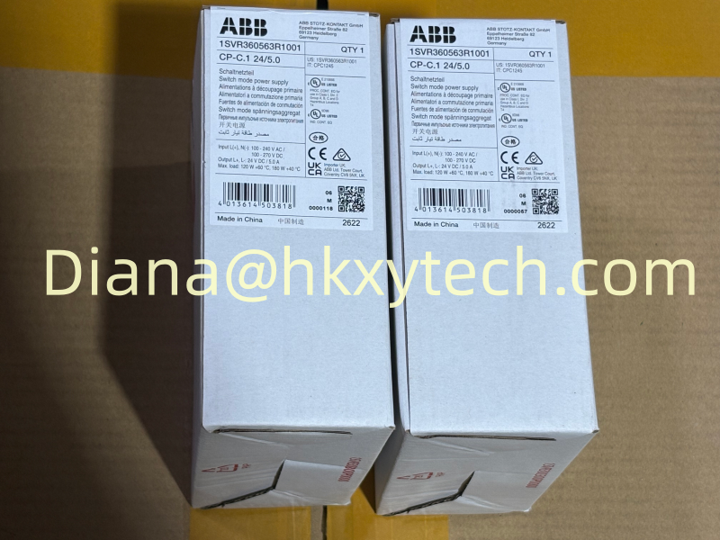
The package labels in the supplied image identify ABB 1SVR360563R1001 and CP-C.1 24/5.0. Receiving inspection should still compare the label, purchase order and current ABB documentation before installation, especially where a legacy panel drawing lists a different input range or accessory arrangement.
Start with a Load Ledger
List every device powered from the 24 VDC bus and separate continuous current from startup, inrush and switched load. Include PLC processors, I/O, relays, transmitters, network switches, valves, indicators and service outlets. The ABB 1SVR360563R1001 has a 5 A rated output, but a design that totals exactly 5 A leaves no allowance for expansion, temperature effects, cable losses or simultaneous switching.
Calculate the worst credible operating state rather than adding only typical currents. A valve bank may energize during a shutdown sequence while communications equipment remains active. The ABB 1SVR360563R1001 offers a power reserve of up to 50 percent under specified conditions, but reserve capacity should support transient demand, not conceal a continuously overloaded panel.
Check the Source Side Separately
ABB lists a wide input range of 85 to 264 V AC and 90 to 300 V DC, with rated input identified as 100 to 240 V AC or 90 to 300 V DC in current product data. Verify branch protection, conductor size, disconnecting method and prospective fault current for the actual supply. The ABB 1SVR360563R1001 includes power factor correction, but upstream coordination still belongs in the panel design.
Keep AC input wiring separated from sensitive DC signal wiring. Confirm protective-earth practice, terminal torque and insulation requirements. If the ABB 1SVR360563R1001 is supplied from DC, verify polarity and ensure maintenance procedures identify the energy source clearly.
Set the Output Voltage at the Load
The adjustable output is useful for compensating controlled voltage drop, but increasing voltage is not a substitute for adequate cable size. Measure voltage at the ABB 1SVR360563R1001 terminals and at the most distant critical load under representative current. Keep every connected device within its permitted input range and record the final setpoint.
Use separate protected branches for logical groups of loads.
Label the positive and return conductors consistently.
Document whether the DC output is grounded or floating according to the system design.
Check voltage drop during the highest switching event.
Reserve test points that do not require disturbing production terminals.
Understand Parallel Capacity and True Redundancy
ABB permits parallel operation of CP-C.1 units to increase capacity and supports redundancy through suitable accessory modules. These are different design objectives. Two supplies directly paralleled for additional current do not automatically provide protected redundancy. For a redundant system using ABB 1SVR360563R1001 units, define load sharing, decoupling, alarm monitoring and the single-fault current requirement.
Test redundancy by removing each source independently while the real critical load is operating. Confirm that voltage remains acceptable and that the failure is annunciated. If one ABB 1SVR360563R1001 cannot carry the required load alone, the system is capacity sharing rather than N+1 redundancy.
Give Thermal Design Enough Space
ABB specifies operation from -25 to +70 degrees C with output capability dependent on temperature, and current product data lists 5 A through +60 degrees C. The ABB 1SVR360563R1001 is 40 mm wide and mounts on a 35 mm DIN rail. Follow the stated mounting position and clearance requirements so heat can leave the unit instead of warming adjacent electronics.
Measure cabinet temperature near the power supply after the panel reaches steady production load. Consider solar heating, enclosure filters, fan failure and neighboring heat sources. A cool workshop test does not prove that the ABB 1SVR360563R1001 will remain within rating in a sealed field enclosure.
Commissioning Sequence
Verify the ABB 1SVR360563R1001 order number and CP-C.1 24/5.0 label.
Inspect DIN-rail engagement, clearance, terminals, conductor preparation and torque.
Energize without load and set the approved output voltage.
Add load groups in stages while recording current and voltage.
Apply the maximum expected operating state and check distant-load voltage.
Test branch faults, alarms and redundancy behavior where applicable.
Capture thermal readings and final settings for the handover file.
Replacement and Maintenance Decisions
Keep the power budget, wiring diagram, fuse schedule, output setpoint and thermal measurements with the asset record. During troubleshooting, measure both input stability and output behavior before replacing the ABB 1SVR360563R1001. Repeated undervoltage may come from overloaded branches, loose conductors or excessive cable drop rather than the supply itself.
For procurement, use the complete ABB 1SVR360563R1001 code and confirm accessories separately. Similar CP-C.1 units have different output currents and order numbers. A disciplined match prevents an apparently compatible power supply from reducing available capacity or changing the panel layout.
The ABB 1SVR360563R1001 delivers the most value when it is treated as the center of a designed 24 VDC system. A verified load ledger, correct source protection, controlled output setting, thermal clearance and proven redundancy strategy help the ABB 1SVR360563R1001 provide stable power for automation assets throughout the panel lifecycle.