
High-Capacity ABB ACS580-01-089A-4 45 kW General-Purpose AC Drive for Precise Pump, Fan, Conveyor, Mixer and Compressor Motor Control
 August
13, 2026
August
13, 2026
Engineering the ABB ACS580-01-089A-4 for Reliable 45 kW Motor Control: Selection Decisions, Installation Risks and Commissioning Evidence
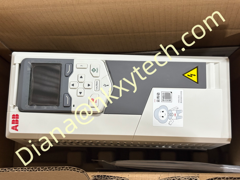
The ABB ACS580-01-089A-4 is a wall-mounted general-purpose drive for industrial motor applications that need controlled speed, practical process regulation and straightforward integration. ABB identifies the ABB ACS580-01-089A-4 at 45 kW, 89 A and 400 V for IEC applications.
This rating makes the ABB ACS580-01-089A-4 relevant to pumps, fans, conveyors, mixers, compressors and other variable- or constant-torque equipment. A reliable project still depends on matching the drive to the real operating duty rather than selecting from motor power alone.
Decision 1: Does the Motor Duty Fit the Drive Rating?
Record motor voltage, full-load current, frequency, rated speed, power factor and insulation condition. Then describe minimum and maximum speed, starting torque, overload duration, starts per hour and normal operating current.
Published IEC reference: 45 kW.
Published current reference: 89 A.
Published voltage reference: 400 V.
Drive family: ACS580-01 general-purpose wall-mounted drive.
Frame reference in current ABB installation material: R4 v2.
The ABB ACS580-01-089A-4 should be checked against the official rating tables for the required duty, ambient temperature and altitude. Any derating or special load condition must be included before equipment is ordered.
Decision 2: What Operating Result Is Expected?
For pumps and fans, the ABB ACS580-01-089A-4 can adjust speed to actual process demand instead of relying only on throttling valves or dampers. Energy performance should be assessed using the real duty profile, operating hours and production output.
For conveyors and mixers, controlled acceleration can reduce mechanical shock and improve repeatability. For compressors, operating limits and minimum-speed requirements must be coordinated with the equipment manufacturer. The ABB ACS580-01-089A-4 should support the process objective without moving the driven machine outside its approved range.
Decision 3: Is the Electrical Design Complete?
Before installing the ABB ACS580-01-089A-4, verify the incoming supply, fault level, protective-device coordination, disconnecting method, conductor size, earthing and motor-cable length. Cable recommendations and protective devices must be selected from the applicable ABB manual and local electrical requirements.
Review EMC practices, control-cable separation and any need for output filtering. Confirm whether braking, bypass, fieldbus, safety or enclosure options are included in the complete ABB ACS580-01-089A-4 order code.
Installation Risks to Eliminate
Restricted cooling: maintain required airflow and service clearances.
Incorrect grounding: follow the specified protective earth and motor grounding arrangement.
Signal interference: separate sensitive control wiring from power and motor conductors.
Undocumented controls: map run commands, references, permissives and fault outputs before removing old equipment.
Wrong option assumptions: verify every suffix in the ABB ACS580-01-089A-4 purchase specification.
Commissioning Evidence - Stage A: Cold Checks
With the equipment isolated, inspect supply terminals, motor connections, protective earth, cable shielding and control wiring. Confirm that the installed hardware and accessories match the approved ABB ACS580-01-089A-4 design.
Evidence required: inspection record, torque verification where required, wiring markup and motor nameplate photograph.
Commissioning Evidence - Stage B: Motor Setup
Enter the exact motor nameplate values, select the approved control mode and perform the required motor identification procedure under safe conditions. Check rotation at a low reference before coupling the process when practical.
Evidence required: saved ABB ACS580-01-089A-4 motor data, direction confirmation and initial current reading.
Commissioning Evidence - Stage C: Loaded Operation
Test acceleration, deceleration, stopping and process response across the planned operating range. Monitor current, speed reference, motor temperature and mechanical behavior. Unexpected current can indicate incorrect motor data, mechanical resistance or unsuitable ramp settings.
Evidence required: operating readings at low, normal and high demand, plus any approved ABB ACS580-01-089A-4 parameter adjustments.
Commissioning Evidence - Stage D: Control Integration
Verify local and remote commands, analog references, fieldbus data, interlocks and alarm outputs individually. Simulate loss of a permissive, communications interruption and restoration after a power loss. The ABB ACS580-01-089A-4 response must match the approved control philosophy.
Evidence required: signed functional test, alarm list and documented restart behavior.
Operational Readiness Checklist
Archive the accepted ABB ACS580-01-089A-4 parameter set.
Store the complete type code and option list with the asset record.
Update electrical drawings and control descriptions.
Define inspection intervals for cooling, contamination and terminals.
Record normal current and process readings for future comparison.
Prepare a spare and restoration plan based on the approved configuration.
Trend operating data rather than waiting only for a trip. Changes in current, loading or alarm frequency can reveal a developing process or mechanical problem before it interrupts production.
The ABB ACS580-01-089A-4 offers a practical platform for 45 kW motor control when the electrical design, load profile and control strategy are treated as one system. Confirm the complete ABB ACS580-01-089A-4 code, enclosure, accessories and regional requirements before ordering, and preserve commissioning evidence so future maintenance has a dependable baseline.