
Robust E+H FMX21-AA121HGD15A+POPS Hydrostatic Level Probe for Reliable Water and Process Measurement
 August
10, 2026
August
10, 2026
Implementing the E+H FMX21-AA121HGD15A+POPS for Stable Hydrostatic Level Measurement: Application Review, Installation and Maintenance
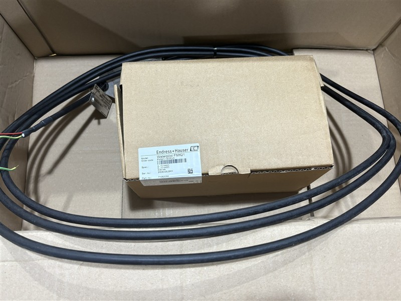
The E+H FMX21-AA121HGD15A+POPS is a configured Waterpilot FMX21 hydrostatic level probe intended for continuous liquid-level measurement. The FMX21 platform uses hydrostatic pressure and an oil-free capacitive ceramic measuring cell to convert the liquid head above the probe into a stable measurement signal. The E+H FMX21-AA121HGD15A+POPS can support water, wastewater and related level applications when its exact configured materials, pressure range, cable and approvals match the process.
Hydrostatic level measurement is simple in principle: pressure at the probe changes with liquid height and density. Accurate results therefore depend on more than the sensor alone. Engineers applying the E+H FMX21-AA121HGD15A+POPS should document liquid density, expected level range, vessel venting, temperature variation, cable length, installation elevation and the location of the atmospheric pressure reference.
FMX21 Platform Reference
| Parameter | Published Platform Information |
| Measuring principle | Hydrostatic pressure |
| Measuring cell | Oil-free capacitive ceramic cell |
| Pressure range | 100 mbar to 20 bar across available configurations |
| Reference accuracy | 0.2 percent; 0.1 percent optional |
| Supply | 10.5 to 35 VDC |
| Communication options | 4 to 20 mA or 4 to 20 mA HART |
| General process temperature reference | -10 to 70 degrees C; configuration-dependent limits apply |
| Maximum measurement distance | Up to 200 m H2O across the product platform |
Confirm the Complete Ordering Code
The suffix in E+H FMX21-AA121HGD15A+POPS represents a configured device, so platform-wide specifications must not be assumed to describe every selected option. Before ordering, compare the complete E+H FMX21-AA121HGD15A+POPS code with the required probe diameter, measuring range, wetted materials, cable material and length, output signal and approvals. This verification protects the project from a mechanically compatible but incorrectly configured delivery.
The measuring range should cover the maximum hydrostatic head with adequate margin while still giving useful resolution over the normal operating span. For the E+H FMX21-AA121HGD15A+POPS, the calculated pressure must include liquid density and the vertical distance between the probe diaphragm and reference level. If density changes significantly with product composition or temperature, the control system may require compensation.
Install for a Stable Pressure Reference
Lower the E+H FMX21-AA121HGD15A+POPS to the specified measurement elevation without striking the ceramic sensing area. The probe should remain clear of agitators, inlet jets, heavy sediment and structures that can create turbulence or mechanical contact. A stilling tube may improve stability in turbulent vessels, provided it is correctly vented and does not trap pressure.
The extension cable is part of the measuring system and must be protected from cuts, crushing and excessive tension. Route the E+H FMX21-AA121HGD15A+POPS cable away from power conductors and support it according to the installation instructions. The atmospheric reference path must remain dry and unobstructed; moisture entering a vented cable or terminal arrangement can create slow measurement drift.
Commission with Independent Level Checks
Before wet commissioning, verify supply voltage, loop polarity and the receiving input range. Check the E+H FMX21-AA121HGD15A+POPS signal in air and confirm that the control-system tag, engineering units and scaling match the approved data sheet. Once installed, compare the indicated level at two or more known points rather than relying on a single zero check.
If HART communication is included in the configured E+H FMX21-AA121HGD15A+POPS, record the device identification, range values, damping and diagnostic status. Any zero-position correction should reflect the physical installation and should not be used to conceal an incorrect range selection or elevation error. Store the final E+H FMX21-AA121HGD15A+POPS configuration with the loop documentation.
Understand Common Sources of Error
A stable but incorrect reading may result from wrong density, incorrect scaling or an elevation offset. A slowly drifting E+H FMX21-AA121HGD15A+POPS signal can indicate vent-path moisture, buildup or changing liquid density. Rapid fluctuations may be caused by turbulence, pumping action or electrical interference. Comparing the transmitter output with a manual level reference helps separate process effects from instrument issues.
For wastewater service, inspect for buildup and mechanical damage at intervals suitable for the process. For water applications, preserve hygienic or drinking-water requirements defined by the project. Never clean the E+H FMX21-AA121HGD15A+POPS ceramic surface with a method that can scratch or shock the sensing element.
Lifecycle Documentation and Replacement Readiness
Maintain a record of the complete E+H FMX21-AA121HGD15A+POPS ordering code, serial number, calibration range, cable length, installation elevation and approved configuration. A spare should match these details, not merely the FMX21 family name. When replacement is required, confirm that the cable termination and loop settings are transferred correctly.
When application conditions are reviewed carefully, the E+H FMX21-AA121HGD15A+POPS provides a robust basis for continuous hydrostatic level measurement. Correct configuration, protected cable routing, independent commissioning checks and clear maintenance records allow the E+H FMX21-AA121HGD15A+POPS to support reliable water and process monitoring over its service life.